Climate Control System
Two climate control systems are used on the 2013 LEAF®. The 2013 LEAF® S has essentially the same climate control system as the previous model with these exceptions:
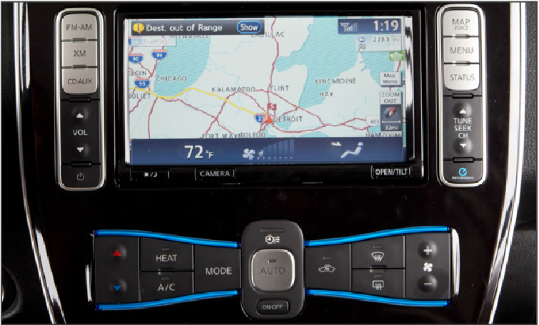
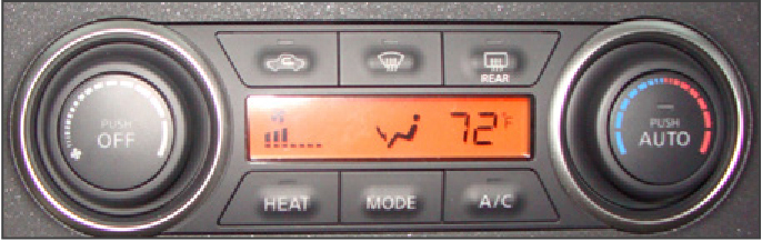
The Panasonic A/C compressor is mounted on the right end of the Traction motor instead of the front. An air-heating PTC heater replaces the water-to-air PTC heater system on the S, SV, and SL models. The new climate control panel includes a HEAT switch.
The water-to-air PTC heater on previous models was replaced with a 5kW airheating PTC heater. The high-voltage harness that supplies power to the PTC heater comes directly from the lithium-ion battery. This the only high-voltage harness that does not attach to the PDM. The PTC heater is installed on the HVAC housing inside the vehicle. It includes a Controller IC, Radiation Panel, Plastic Frame, and PTC Elements.
A PTC heater is used as the heat source for heating. The Positive Temperature Coefficient (PTC) is a ceramic material with barium titanate as the primary component. The PTC heater provides an internal control circuit and performs LIN communication with A/C auto amplifier. Based on the signals from A/C auto amplifier, the microcomputer inside PTC heater controls the heater output by PWM. When current is applied, it heats up. Upon reaching a certain temperature (Curie temperature) the resistance suddenly increases, limiting the current, and maintaining a constant amount of heating.
The PTC heater operates at temperatures below 68 degrees Fahrenheit.
Note:
Never disassemble the PTC heater. Replace it as a unit. Before replacing the PTC heater, power down the high-voltage system and verify it’s safe.
LEAF® SV and SL models use an efficient heat pumptype air conditioner system to provide both heat and cooling. The heat pump and PTC heater systems provide the same output but use less than a 1/3 of the energy of the previous system. The climate controlled system includes: a Denso A/C compressor, an evaporator, an inside condenser, an outside condenser, and an accumulator. It uses fixed orifices instead of a thermo-expansion valve, one on the evaporator inlet, and one on the inside condenser outlet. A three-way solenoid valve controls refrigerant flow through the evaporator. An ON/OFF solenoid valve is used to bypass the fixed orifice on the inside condenser outlet.
Heat Pump System
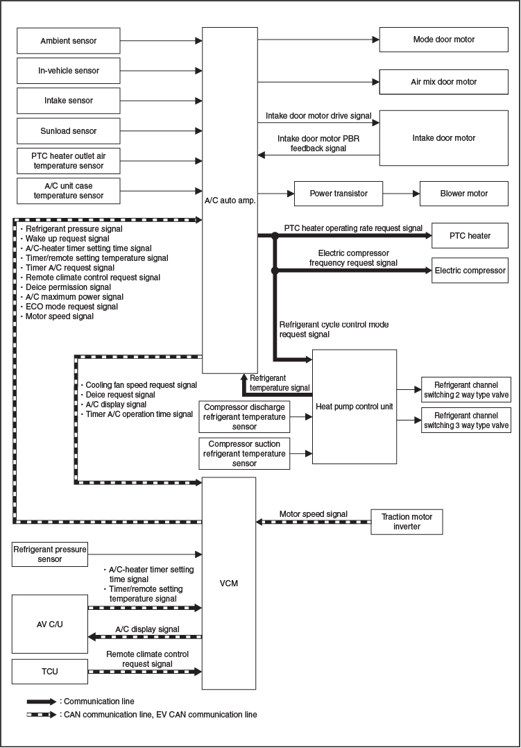
The automatic air conditioning system is controlled by the control functions of the A/C auto amplifier, VCM, AV control unit, heat pump control unit and TCU. The A/C system operations are input from the A/C auto amplifier switches (A/C control). The A/C auto amplifier sends various display information to the VCM via EV CAN communication. The VCM sends information received from the A/C auto amplifier to the AV control unit via EV CAN communication. The AV control unit displays the A/C status on the display, based on the information received from VCM. The A/C auto amplifier transmits each type of request signal to PTC heater, electric compressor and heat pump control unit via LIN communication for controlling the PTC heater, electric compressor and heat pump system.
The heat pump control unit performs LIN communication with the A/C auto amplifier. It receives the signals from the compressor discharge refrigerant temperature sensor and the compressor suction refrigerant temperature sensor and converts them to voltage values to transmit to the A/C auto amplifier. The control unit is responsible for switching of the two-way valve and the three-way valve from the request signal from the A/C Auto amplifier.
The A/C auto amplifier controls A/C by calculations based on signal input from each sensor and switch. A self-diagnosis function is integrated into the A/C auto amplifier, allowing diagnosis of the automatic air conditioning system to be performed quickly.
The two- and three-way valve, controls the flow of refrigerant for cooling or heating applications. The two-way valve blocks the flow of refrigerant forcing it to go through the heating orifice tube. The three-way valve is used to force refrigerant through the cooling orifice tube and evaporator or to bypass both of these components to provide heat for the passengers.
The inner condenser is located in the heating and cooling unit inside the vehicle and is used to heat the air blown across it by the blower motor.
When the conditions for electric compressor operation are met while the blower fan motor is operating, based on the various input signals, the A/C auto amplifier calculates the electric compressor target speed. This target speed produces: the target temperature (cooler and dehumidified) mode of 39°F to 54°F (4°C to 12°C), the heater mode (target outlet temperature plus corrected temperature value) for the evaporator outlet temperature (cooler and dehumidified mode), or the inner condenser temperature (heater mode). It then sends a speed request signal to the electric compressor via LIN communication and commands the speed.
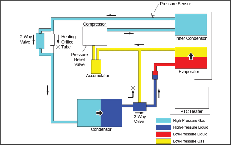
Heat Pump Refrigerant Flow for Cooling
During the cooling operation, the three-way valve and the ON/OFF solenoid valve are open. The system operates like a conventional A/C system to cool the cabin. The heater orifice is bypassed; the evaporator orifice causes a pressure change and cooling occurs.
The path of refrigerant flow is from the electric compressor to the inner condenser and then through the two-way valve and onto the condenser, where it is cooled. After cooling, it goes through the cooling orifice tube and then to the evaporator and finally to the accumulator before returning to the electric compressor. The vaporization of evaporator refrigerant is controlled by the orifice tube. If the air temperature after passing through the evaporator (detected by the intake sensor) is 34°F (1°C) or less, the A/C auto amp. sends a request for the electric compressor to be turned off. Based on this signal from A/C auto amp., the electric compressor stops.
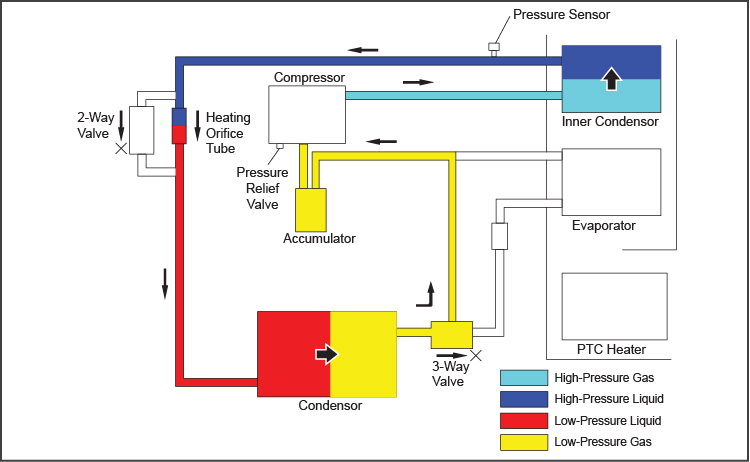
Heat Pump Refrigerant Flow for Heating
In heater mode, both the three-way valve and the ON/OFF solenoid valve are closed. The evaporator is bypassed and the heater orifice is where the pressure change occurs. Heat from the outside air is then transferred to the outside condenser which acts like the evaporator. In heater mode, the PTC heater supplements the heat pump system to warm the cabin. Temperature sensors are located in the suction and discharge side of the compressor. A pressure sensor is located in the discharge side of the A/C compressor. These are inputs to the heat pump control unit. A temperature sensor sends the discharge air temperature to the HVAC control unit. The HVAC control unit calculates the variance from the target output temperature during heat mode. It adjusts and controls the compressor speed and the PTC heater ON or OFF operation to achieve the target temperature.
The three-way valve directs the refrigerant back to the accumulator and onto the electric compressor, bypassing the evaporator. The refrigerant is heated as it is compressed by the electric compressor. The condensing of refrigerant inside the inner condenser provides interior heat.
De-ice Mode
A de-ice mode prevents the outside condenser from icing over if the climate control system is in pre-conditioning mode during charging. During de-icing operation, the 3-way valve is closed and the ON/OFF solenoid valve is open. This circulates pressurized refrigerant throughout the system, to warm the outside condenser and melt the ice.
Timer Function
In the previous LEAF® model, the target climate control temperature during preconditioning was fixed at 77°F. On the 2013 LEAF® the target preconditioning temperature setting can be adjusted in the NAVI system. Remote activation of the preconditioning mode is available on the SV and SL models, but not available on the S model. This value needs to be reset if the battery is disconnected.