The Continuously Variable Transmission (CVT) allows engines to work at their greatest potential by freely moving through gear ratios to maximize performance and fuel economy. The advantage of the CVT is that it can choose the optimum transmission gear ratio. Solid gears are a thing of the past. The CVT uses the readings of multiple sensors to keep the engine rotating at a precise number of RPM with two variable pulleys and a steel belt. The system consists of seven smaller systems, including the vehicle’s mechanical, electrical, and oil systems, to provide fuel efficiency and continuous power. The following information on the CVT will guide you through its history, the systems and components involved and their operation.
HISTORY AND EVOLUTION OF CVT
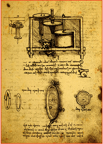
The first visionary that conceptualized a stepless, continuously variable transmission was none other than painter, architect and inventor Leonardo da Vinci. He first sketched a stepless, continuously variable transmission in 1490.
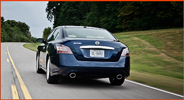
In the centuries that followed, Adiel Dodge received a U.S. patent for a toroidal CVT. It still took years before the continuous variable transmission idea was brought to fruition in sawmills, tractors and motorcycles. Nissan® first used the CVT in the 1992 March, which was a super mini car also known as the Micra. The cube® and the Primera, which was introduced as the Infiniti G20® in North America, also ran with CVTs. After extensive research and development, Nissan developed a CVT that would run in high-torque engines in 2002. Nissan introduced the Xtronic CVT® with the release of the Murano in 2003. It was designed to provide smoother, quieter, and virtually shift shock free transmission performance at higher MPG than the traditional A/T. Now, the Xtronic CVT is found in all of Nissan’s front-wheel drive car models.
Nissan has continued making design changes ever since the CVT first hit the streets in North America. The newest models of this transmission are lighter and shorter and utilize optimum hydraulic control technology, which has enabled their use in a wider range of vehicles. They also have a broader gear ratio range by an entire gear, up to 7.3:1 in some vehicles from 6.0:1, providing fuel efficiency at a greater range of speeds.
CVT BASIC OPERATION
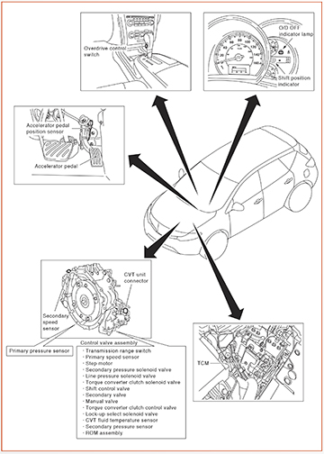
Nissan’s Xtronic CVT is a complex system that involves the use of sensors from the combination meter, the gear shifter and under the hood on both sides of the vehicle.
It is important to understand gears before we move forward. The rotating axes on a bicycle are gears. Imagine the bicycle with just two gear axes, both capable of expanding or contracting to the size of the largest and smallest gears that were on the bike, and you have imagined a continuously variable transmission. The CVT’s gears are capable of changing rotational direction, changing the speed of rotation, and optimally pairing the rotational speeds of the two axes.
When the driver presses the accelerator pedal, this sends a slew of signals to the CVT’s control valve assembly and the Transmission Control Module (TCM). The TCM controls the oil pressure system, which has two valves that control line pressure. The other signals are translated to voltages to activate the entire transaxle, including two variable pulleys and one steel-plated belt. The pulleys constantly adjust themselves to stay in the proper ratio. At around 5 MPH (8 km/h), the lock-up converter and the select control system engages, reducing slippage to get the best possible fuel efficiency. Contributors to the CVT’s functionality include the pulleys, belt CVT control valve assembly, shift lock system, oil pressure control system, fluid warmer system and the lock-up and select control system.

CVT SYSTEMS – Transaxle
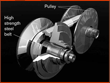
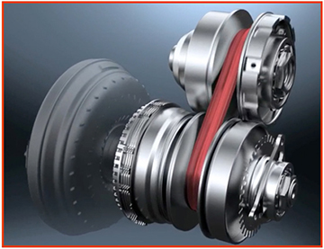
Pulleys and Belt – The two pulleys and the belt are the heart of the CVT system. The primary, or drive pulley, connected to the engine lies on the input shaft side. The secondary, or driven pulley, lies on the output shaft side to the drive wheels. There is a cone-shaped slope on the fixation sheave half of the pulley that works with the slope on the mobile sheave halves that can move in the axial direction.
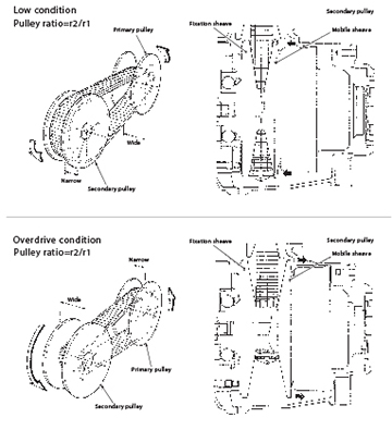
The movable sheave slides on the shaft to change the groove width of the pulley. As the pulley sheave halves come closer together and the width of the pulley changes, the belt is forced to ride higher on the pulley, effectively making the pulley’s diameter longer. Changing the diameter of the pulleys varies the transmission’s ratio (the number of times the output shaft spins for each revolution of the engine). Making the output pulley diameter longer gives a low ratio (a large number of engine revolutions producing a small number of output revolutions) for low-speed acceleration.
Input signals of engine load (accelerator pedal opening), primary pulley speed and secondary pulley speed change the operation pressures of the primary pulley and the secondary pulley and control the pulley groove width. As the car accelerates, the pulleys vary their diameter to lower the engine speed as the car speed rises, continuously varying the ratio.
Force on the belt is generated when oil pressure is applied to the secondary pulley to nip or squeeze the plate, and the plate is pushed outward. The steel ring on the belt offers resistance, and pulling force is generated. The plate of the primary pulley is nipped as well. Lastly, friction force is created between the steel belt and the primary pulley.
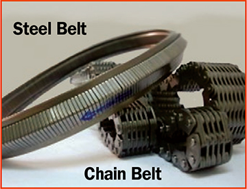
Chain Belt – The chain belt consists of approximately 150 locker pins and 1,000 link plates. Chains are rotated by locker pins sandwiched by pulleys. This produces the tension difference in chains among pulleys, and accordingly, the power is transferred by the tension.
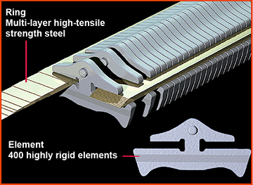
Pulleys and Belt - The heart of the CVT system
As the belt rides higher on one pulley and lower on the other it changes the arc radius of the belt. This effectively changes the diameters of the pulleys, which controls the gear ratio.

Steel Belt – The introduction of the steel belt is one of the more important advances in the design and development of the CVT. The steel belt is made of multiple steel plates and two steel rings.
The pulley’s groove width is changed freely in the axial direction according to acceleration from low status to overdrive status continuously. The belt is controlled by the oil pressure signals of the primary and secondary pulleys. The pulley’s width is changed by the movable sheave inside the belt. The wider the pulley becomes, the shorter its rotation. To change the size of the pulley, the sheave moves along the fixed plate, or shaft.
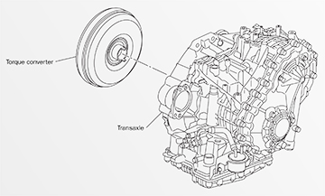
Torque Converter
The torque converter transmits torque to the transaxle. The converter has a lock-up function.
Input Shaft
The input shaft is connected to the forward clutch drum. It transmits the traction force from the torque converter to the clutch drum.
Torque Converter Regulator Valve - The torque converter regulator valve regulates feed pressure to the torque converter by choosing the optimum pressure for the driving conditions.
Pressure Regulator Valve - The pressure regulator valve adjusts the discharge pressure from the oil pump in the line for driving conditions.
Torque Converter Clutch Control Valve - The torque converter clutch control valve adjusts the torque converter clutch engage and disengage pressures according to information from the TCM and the torque converter clutch solenoid valve.
Shift Control Valve - The shift control valve controls the line pressure that is applied to the primary pulley according to the stroke difference between the step motor and the primary pulley.
Secondary Valve - The secondary valve reduces oil line pressure and adjusts secondary pressure.
Clutch Regulator Valve - The clutch regulator valve adjusts clutch-operating pressure according to the driving conditions.
Manual Valve - The manual valve distributes clutch operation pressure to each circuit according to the selector lever position.
Select Control Valve - The select control valve adjusts forward clutch pressure and reverse brake pressure.
Select Switch Valve - The select switch valve’s job is to perform switching control of the torque converter clutch solenoid valve control pressure when lock-up is engaged/disengaged.
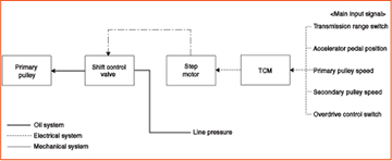
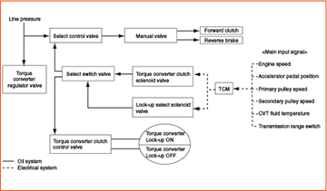
This diagram shows the flow of information and action from the input signals received by the TCM to the CVT control valves, to the oil pump and to the engine cooling system.
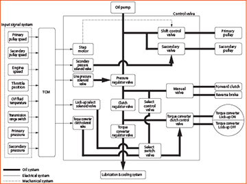
Accurate line pressure and secondary pressure control reduces friction for better fuel economy. When an input torque signal equivalent to the engine driving force is transmitted from the ECM to the TCM, the TCM controls the line pressure solenoid valve and secondary pressure solenoid valve. The diagram shows how the oil pressure is set. The determinate factors for oil pressure control are: accelerator pedal position, engine speed, primary pulley (input speed), secondary pulley (output speed), input torque, stop lamp switch signal, transmission range switch signal, lock-up signal, power voltage, target shift ratio, oil temperature, and oil pressure.
Fluid Warmer System
The CVT’s fluid warmer system has two parts: the CVT oil warmer and the heater thermostat. Engine coolant warms faster than CVT fluid. In order for the CVT fluid to warm up quickly, which saves fuel, the oil warmer found on the front of the transaxle makes it so the engine coolant and the oil help warm the CVT fluid. The heater thermostat is on the front of the transaxle as well.
CVT Control System
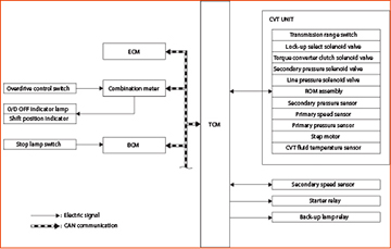
The CVT’s control system incorporates the mechanical, oil, and electrical systems and has multiple locations in the vehicle and under the hood. The TCM receives signals from sensors in order to judge driving conditions and control the variable speed mechanism. Some of them are located in the CVT control valve assembly and some are found in the transaxle assembly.
Transmission Range Switch - The transmission range switch tells the TCM the selector lever’s position.
CVT Fluid Temperature Sensor - The CVT fluid temperature sensor uses a thermistor for measurement and control. A thermistor is a ceramic resistor. It converts changes in the CVT fluid temperature to a resistance value. That value is the number that the TCM uses to evaluate the CVT fluid temperature.
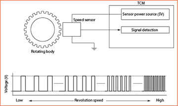
Primary Speed Sensor - This sensor is found in the control valve assembly. It detects the primary pulley revolution speed, generating the ON/OFF pulse in proportion to the rotating body speed. The higher the rotating body speed, the faster the change cycle. The change cycle of the pulse signal helps the TCM judge rotating speed.
Secondary Speed Sensor - The secondary speed sensor is found in the rear of the transaxle assembly. Its duties are the same as the primary speed sensor, but for the secondary pulley.
Primary Pressure Sensor - The primary pressure sensor, found in the transaxle assembly, detects the primary pressure of the CVT and sends a signal to the TCM. Deformation of a ceramic device in the secondary pressure sensor results in a voltage change. The change helps the TCM evaluate secondary pressure. If the pressure is up, the voltage is also up.
Secondary Pressure Solenoid Valve - The secondary pressure solenoid valve is located in the control valve assembly. It contains a linear solenoid valve and it controls the secondary valve.
Linear Solenoid Valve - The linear solenoid valve is part of the secondary pressure solenoid valve. Its purpose lies in the idea that the pressing force on the valve spool in the coil of the solenoid valve increases in proportion to the valve’s current. It produces hydraulic control when it is not energized.
Line Pressure Solenoid Valve - This valve contains a linear solenoid valve, and it controls the pressure regulator valve.
Torque Converter Clutch Solenoid Valve - This valve is a linear solenoid valve, and it controls the torque converter clutch control valve in the transaxle assembly.
Lock-up Select Solenoid Valve - This valve controls the select switch valve and contains the ON/OFF solenoid valve. It engages to prevent slippage.
Step Motor - This motor controls the pulley but does it so smoothly that there is no step. This motor turns four coils ON/OFF according to the signal from the TCM. As a result of its actions, the flow of line pressure to the primary pulley is changed controlling pulley ratio.
ROM Assembly - This Read Only Memory (ROM) assembly stores the characteristic value of each solenoid valve and sends it to the TCM, which allows accurate hydraulic control via this data.
Shift Position Indicator - Shift position indication is displayed according to signals from the TCM via CAN communication.
Overdrive Control Switch (if so equipped) - The O/D button on the shift knob turns O/D ON and OFF.
O/D OFF Indicator Lamp (if so equipped) - The O/D Indicator light is found on the combination meter. It turns on for a short amount of time when overdrive is OFF and the ignition is ON.

LOCK-UP AND SELECT CONTROL SYSTEM
Lock-up solenoids lock torque converters in place to prevent slippage in automatic transmissions under certain circumstances such as traveling on the highway. The current CVT has the lowest lock-up speed of all Nissan CVTs to date, which is somewhere around 5 MPH (8 km/h), greatly improving fuel economy.
When lock-up is applied, the torque converter clutch control valve presses and couples the torque converter clutch piston. When lock-up is released, the pressure is drained and the Torque Converter Clutch (TCC) piston is not coupled.
The precision of this system is achieved via a signal from the TCM to the TCC solenoid valve to the TCC control valve to release or engage the TCC piston. The TCC solenoid valve controls engagement of the forward clutch and the reverse brake. The lock-up and select control system diagram is pictured below.
Note that when the torque converter control locks up the CVT, it solidifies the connection between the engine output shaft and the transmission input shaft. This effect eliminates slippage in the torque converter, reduces operating temperature, and makes the CVT the most fuel efficient, but the pulleys still change ratio/positioning.
SHIFT CONTROL SYSTEM
The shift control system brings everything together in a smooth fashion. The TCM receives electrical signals from the transmission range switch, accelerator pedal position sensor, both pulleys and the overdrive switch. The TCM then does two things: It uses the signals to control inflow/outflow of line pressure for oil to the pulleys and sends a mechanical signal to the shift control valve to direct it to a particular gear ratio by way of pulley position.