
The Nissan® Pathfinder® and Infiniti® QX60™ are available with the first specialized unit suited for hybrid SUVs that are equipped with belt-type CVTs.
The RE0F02H makes use of significant friction reduction and wider ratio coverage which has a 17% improved ratio spread over the previous generation CVT.
The RE0F02H uses a sophisticated clutch control technology for engaging or disconnecting the engine in the converter housing of the CVT. It was designed for efficient energy regeneration and motor drive for parallel hybrid vehicles. It is intended to provide both fuel-efficient performance and high-level drive performance.
PRODUCT CHARACTERISTICS
- The RE0F02H is a parallel hybrid transmission.
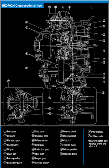
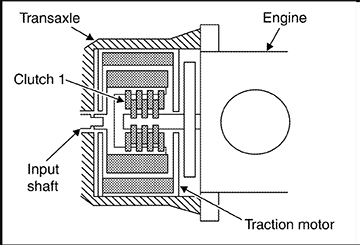
- The design structure utilizes a one-motor, two-clutch system inside the converter housing that uses the FR7AT as the base, replacing the torque converter in the CVT.
NOTE: One clutch is installed between the gasoline engine and the electric motor, the other within the CVT.
- Reduced size and weight and enhanced transmission efficiency helps improve fuel economy, power performance, and gear change performance, thus providing a powerful drive with a sense of directness and linearity.


CLUTCH 1
Clutch 1 is included in the traction motor assembly. Clutch 1 is a dry and multiple type clutch that consists of a clutch drum, piston, drive plate and driven plate.
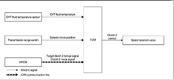
CLUTCH 2 CONTROL
The TCM activates the select solenoid valve according to a clutch 2 mode signal received from the HPCM; the select solenoid valve controls the transfer torque of clutch 2.
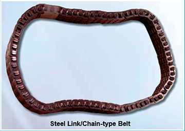
The engine-to-transmission ratios were improved over earlier models with the use of a sturdy chain instead of a belt, giving strong, smooth acceleration and lower revs when cruising.
The chain belt consists of approximately 150 locker pins and 1,000 link plates. Chains are rotated by locker pins sandwiched by pulleys. This produces tension difference in chains among pulleys. Accordingly, the power is transferred by the tension.
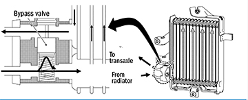
CVT FLUID COOLER
The CVT fluid cooler is installed on the vehicle front. The CVT fluid cooler helps prevent CVT fluid temperature from an abnormal increase while driving the vehicle. CVT fluid is directed into the fluid cooler where it is cooled by air while driving the vehicle before it enters the transmission.
BYPASS VALVE
The bypass valve is installed on the CVT fluid cooler to control the CVT fluid flow.
When CVT fluid temperature is low, the bypass valve is open. Most of the CVT fluid therefore returns to the transaxle without flowing into the cooler core that has larger flow resistance.
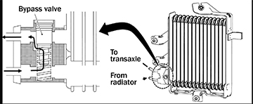
When CVT fluid temperature rises to approximately 149°F (65°C), the bypass valve fully closes and allows the CVT fluid to flow into the cooler core. CVT fluid flowing into the cooler core is cooled by the air stream that is caused by vehicle travel and returned to the transaxle.
HEATER THERMOSTAT
The heater thermostat is installed on the front part of the transaxle assembly. The heater thermostat opens and closes at a set temperature.
THE CVT FLUID TEMPERATURE SENSOR
The CVT fluid temperature sensor detects CVT fluid temperature in the oil pan. The fluid temperature sensor uses a thermistor and changes the signal voltage by converting changes in the CVT fluid temperature to a resistance value. The TCM evaluates the CVT fluid temperature from the signal voltage value.

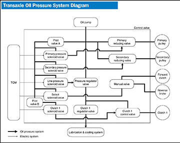
OIL PUMP
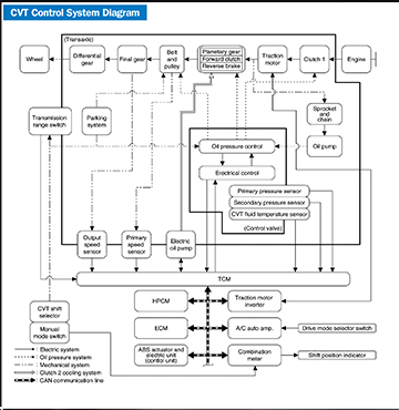
The oil pump is a vane-type pump that is driven by the engine/traction control motor through the oil pump drive chain. This pump increases efficient discharge volume in the low-speed zone and optimizes pump discharge volume in the high-speed zone. Discharged oil from the oil pump is transmitted to the control valve for primary and secondary pulley operation and for clutch operation and lubricates each part. The oil pressure required for operation of the transaxle transmission mechanism is generated by the oil pump, oil pressure control valve, solenoid valve and others shown in the diagram.
ELECTRIC OIL PUMP
The electric oil pump contains a “three-phase brush-less synchronous motor.” The electric oil pump is controlled by the TCM to supply the necessary cooling oil for clutch 2. The electric oil pump operates according to a status signal transmitted from the TCM via the PWM (Pulse Width Modulation).