
The vehicle’s driving status is judged based on the signals from various sensors, switches and other control units in order to provide optimal transaxle control.
ENGINE AND CVT INTEGRATED CONTROL
According to the vehicle’s driving conditions, the ECM and TCM exchange signals to apply real-time cooperation for the purpose of controlling the way the vehicle feels when shifting speeds by preventing drops in engine speed.
NOTE: “Engine and CVT integrated control signal” is the general term used to describe the communication (torque-down permission, torque-down request, etc.) that is exchanged between the ECM and TCM.
- The TCM receives the following input signals via CAN communication from the ECM:
- Engine speed signal
- Accelerator pedal position signal
- Closed throttle position signal - The TCM transmits the following signal via CAN communication to the ECM:
- Malfunction Indicator Lamp signal
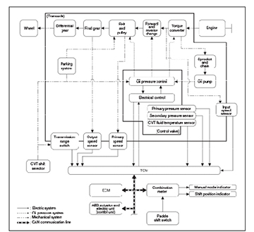
CVT CONTROL SYSTEM
The TCM consists of a microcomputer and connectors for signal input and output and power supply. The TCM judges the vehicle’s driving status, determines the required line pressure, shifting point, and lock-up operation, and sends the required output signals to the step motor and the respective solenoids.
When an input torque signal equivalent to the engine drive force is sent from the ECM to the TCM, the TCM controls the line pressure solenoid valve and secondary pressure solenoid valve. This line pressure solenoid controls the pressure regulator valve as the signal pressure and adjusts the pressure of the CVT fluid discharged from the oil pump to the line pressure most appropriate to the driving condition. Secondary pressure is made by line pressure decreasing.
The TCM has an electrical fail-safe mode. The mode functions so that operation can be continued even if the signal circuit of the main electronic control input/output parts is damaged. If an unexpected signal is received or there is an error in a main electronic control input/output signal circuit, this protection control mode helps maintain function of the sensors, solenoids, torque converter, and step motor so that operation can be continued.
If the vehicle exhibits a behavior, or a condition such as “poor acceleration,” a malfunction of the applicable system is detected by TCM and the vehicle may be in a fail-safe mode. At this time, check the DTC code and perform inspection and repair according to the malfunction diagnosis procedures described in the ESM.
CVT PROTECTION CONTROL
Some examples of TCM protection controls are:
CONTROL FOR WHEEL SPIN
When wheel spin is detected, the engine output and gear ratio are limited and the line pressure is increased. It limits engine output when a wheel spin occurs in any right- or left-drive wheels.
TORQUE IS REDUCED WHEN DRIVING WITH THE REVERSE GEAR
Engine output is controlled according to vehicle speed while driving in reverse. Power performance may be lowered while driving in reverse.
CONTROL WHEN FLUID TEMPERATURE IS HIGH
When the CVT fluid temperature is high, the gear shift permission maximum revolution and the maximum torque are reduced more than usual to prevent an increase of the oil temperature. If an unexpected signal is sent from the CVT fluid temperature sensor to the TCM, the gear ratio in use before receiving the unexpected signal is maintained or the gear ratio is controlled. Power performance may be lowered when compared to normal control. The control returns to normal when the CVT fluid temperature is lowered.
REVERSE PROHIBIT CONTROL
The reverse brake is controlled to avoid becoming engaged when the selector lever is set in the R (Reverse) position while driving in a forward direction at more than the specified speed. If the selector lever is moved to the R (Reverse) position when driving in a forward gear, the gear becomes neutral, not reverse. The control returns to normal operation when the vehicle is driven at low speeds.
LINE PRESSURE CONTROL
Highly accurate line pressure control (secondary pressure control) helps reduce friction for improvement of fuel economy.
NORMAL OIL PRESSURE CONTROL
The appropriate line pressure and secondary pressure are determined by the vehicle’s driving condition. Normal oil pressure control is based on: the accelerator pedal position, engine speed, primary pulley (input) speed, secondary pulley (output) speed, vehicle speed, input torque, stop lamp switch signal, transmission range switch signal, lock-up signal, power voltage, target shift ratio, oil temperature, oil pressure, and overdrive control switch signal.
SECONDARY PRESSURE FEEDBACK CONTROL
In normal oil pressure control and oil pressure control in shifting, highly accurate secondary pressure is determined by detecting the secondary pressure using an oil pressure sensor and by feedback control.
SHIFT CONTROL
To select the gear ratio that can give the driving force to meet the driver’s intent or vehicle situation, the vehicle driving condition such as vehicle speed or accelerator pedal position is detected and the most appropriate gear ratio and shift control are determined before reaching the speed. This information is outputted to the primary pressure solenoid valve and secondary pressure solenoid valve to control the line pressure input/output to the pulley. The line pressure inputted/outputted determines the pulley (movable pulley) position to control the gear position.