ELECTRICAL
RESISTANCE AND VOLTAGE DROP
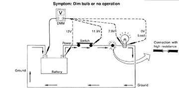
The purpose of voltage in a circuit is to provide the required electrical energy to operate a load. Resistance and voltage drop across a load (such as a light bulb) are required for circuits to work correctly. But, in the wrong place (such as corrosion in a connector) resistance and voltage drop may causes electrical issues, such as dim bulbs, slow motors, heated wires, etc.
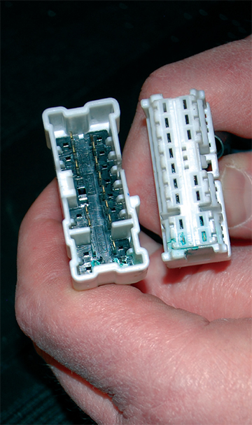
A load can be defined as anything that causes resistance. This includes the wires and devices like switches, diodes, bulbs, or motors, etc. But, resistance can also be created by partial connectivity caused by loose terminal pins, pitted relay contacts, loose connections, or even corrosion. If a circuit has excessive resistance, it prevents the wire or component from carrying sufficient current under high load conditions. In a normally operating circuit, normal resistance is small enough that it doesn’t keep the load from operating properly.
When measuring voltage in a circuit, you’ll find that it is lower after the load (resistance) than it was before the load. The “voltage drop” or the amount that voltage lowers as it goes through a load is an indication or measure of how much electrical energy was used when it was converted into another form of energy (light, heat, or electromagnetic movement). The reason for using a voltage drop test rather than just an ohm meter to measure resistance, is that sometimes a resistance is not evident (not measureable) unless the circuit is placed under load.
When thinking of current in a circuit, sometimes it is helpful to visualize voltage as pressure and amperage as volume. One volt is the amount of electrical pressure needed to move one amp of current through one ohm of resistance.
- Excessive voltage drop caused by high resistance can be identified by inoperative components, slower than normal electrical motor speeds, or even dim or intermittent flickering lamps.
- You should always check connections that are part of the circuit you’re working with just to make sure they are clean, tight or snapped together properly. If a light is dim, start with the simplest checks: the bulb and connectors. While you are at it, don’t overlook potential errors from past repairs. It’s possible the bulb is good, but the wrong bulb was installed previously.

Every part of an electrical circuit (wires, connectors, switch contacts, bulbs, motors, etc.) has some resistance. Most of the time we want that resistance to be very low,
allowing for free flow of current through the circuit.
A multi-meter measures resistance in ohms. The ohmmeter function on a multii-meter is powered by an internal battery. It is used to apply a small voltage to a circuit
or component and measure how much current flows through it, and then display the result as ohms of resistance.
Note: Before starting a test always check the ESM. Some vehicle circuits may have a resistor intentionally installed to reduce voltage and current. Examples include the rheostat that dims the instrument panel lights, ballast resistors in some fuel injector circuits, and motor resistors used to limit blower fan and electric fuel pump speeds. Be sure you know your circuit and identify any "intentional" resistance that can give high ohm reading or high voltage drop readings. Also, the ESM often has specifications for electrical testing.

- If you try to measure the resistance of a component in an operating circuit you will obtain false readings and you may damage the meter.
- If you try to measure resistance of a component while still connected in a circuit you will obtain false readings (even if the power source is disconnected) and you may damage the meter.
- To measure the resistance of a component it must be disconnected (isolated) from its circuit.
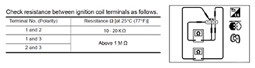
- Check the ESM for specifications. When checking resistance of a component, it's good to know what the resistance value should be.
- Also, before doing a resistance test on electronic components, make sure to check the ESM. Voltage from the ohm meter could damage electronic components if applied to the wrong circuit.
Because the ohm meter is using internal power to test a circuit, it is important to make sure the circuit you are testing is isolated (disconnected) from any power source that may affect the ohm reading or damage the meter.

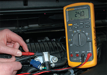
Voltage drop testing provides a method for determining the amount of voltage that is being used by a wire or a component while the circuit is operating (under load).
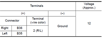
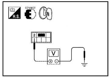
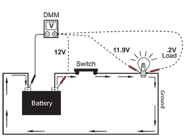
When perfroming a voltage drop test as shown in this example; the volt meters positive lead should be connected to the circuit in the direction of the power source and negative lead toward the ground.
Operate or turn ON the circuit. Voltage will always follow the path of least resistance. So, if there is excessive resistance in the circuit, your meter becomes the path of least resistance for some voltage and will give a voltage reading.
NOTE: Voltage drop across a switch or relay should never exceed 0.3 volts (300mV). But less than 0.1 (100mV) is best.

In this example above;
When testing circuits, you’ll often need to test the voltage at various points. A voltage drop can occur in any part of a circuit.
Meter #1
12 volts at the battery
Meter #2
0 volt reading between the battery positive post and the switch. The wire has no resistance so all of the
voltage goes through the wire and none goes through the meter, giving a 0 volt reading - no voltage drop.
Meter #3
0.1 volt drop across the switch. The switch has a small resistance. 11.9 volts goes through the switch and the remaining voltage (0.1 volts)
goes through the meter, giving a voltage drop reading of 0.1 volts.
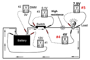
Meter #4
4.0 volt drop across the damaged wire. The wire has high resistance at the fault point, allowing only 79 volts
through the wire. The remaining 4 volts takes the path of least resistance through the meter giving a voltage drop reading of 4 volts. A voltage drop this high will likely cause problems, such as a dim bulb.
Meter #5
At this drop test location, we know that the 0.1 volt drop across the
switch, and the damaged wire equal a voltage drop of 4.1 volts, leaving only 7.9 volts at the positive
side of the bulb. This reading confirms that there is a 4.1 voltage drop in the circuit.

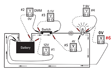
Meter #6
0 volt reading between the battery negative post and the bulb. The wire has no resistance so all of the voltage goes through the wire
back to the battery. No voltage goes through the meter, giving a 0 volt reading - no voltage drop.
Whenever a fault is suspected, both sides of the circuit should be tested. A complete circuit
requires a source (positive side), load (light bulb, motor, etc), and ground (negative side). Always inspect both sides of the circuit. The ground side is often overlooked.
- Voltage drop tests are usually performed when a load fails to operate properly. By this, it may be assumed a voltage drop is not good. But, voltage drops can be good or bad; it all depends on where they occur.
- Good voltage drops are essential. Loads won't work without them. Available voltage must be dropped across the load, or it cannot work. But a high voltage drop in the wrong place (connector, switch, ground point, or wire) is BAD.
- A high voltage drop in the wrong places steals electrical energy from the circuit converting it into heat, causing the circuit to operate poorly.
TIP: Is it Always Practical to Test Right at the Load? No, you may not always be able to have direct access to the load. For instance, you cannot connect your meter leads across the terminals of an in-tank fuel pump. You can only perfrom a voltage drop test on those parts of the circuit accessible to your meter leads.