Voltage Drop and Resistance Measurement
Basic Electrical Diagnostic Troubleshooting
Whenever you approach electrical diagnostic troubleshooting, it’s good to get back to the basics. As you know, the purpose of voltage in a circuit is to provide the required amperage to operate a load. As current flows through a load, it is converted to light, heat, or electromagnetic movement. When measuring voltage in a circuit, you’ll find that it is lower after the load (resistance) than it was before the load. The “voltage drop” or the amount that voltage lowers as it goes through a load is an indication or measure of how much electrical energy was used when it was converted into another form of energy (light, heat, or electromagnetic movement).
What are we checking for? The causes of many common problems in a circuit are opens and current drains or shorts.
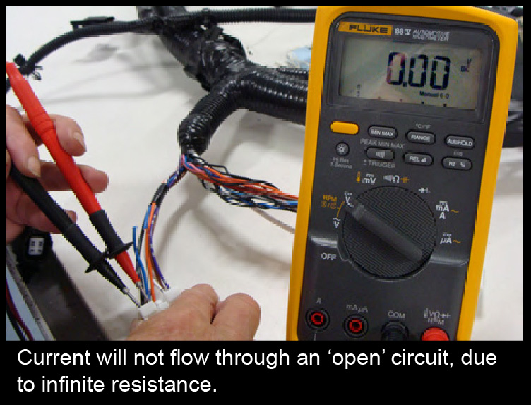
Open Circuits
In order for the flow of electricity to occur, the circuit must be live (requires voltage) and in a closed loop.
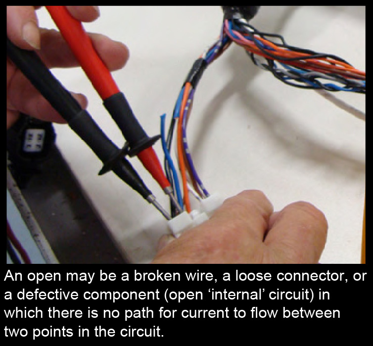
An open circuit causes components or systems to stop working and occurs when there is a break in the flow of electricity. An “open” is usually enough to stop the flow of electrons in the circuit. An open may be a broken wire, a loose connector, or a defective component (open ‘internal’ circuit) in which there is no path for current to flow between two points in the circuit.
Short Circuits
A load can be defined as anything that causes resistance. On our vehicles we know this includes the wires and devices like switches, diodes, bulbs, or motors, etc. But, resistance can also be created by partial connectivity caused by loose terminal pins, loose connections, or even corrosion. A short circuit is an abnormal connection between two points of a circuit. If this is occurring, it can create a path of low resistance through which excessive current can flow, causing systems or components to operate incorrectly or even stop working because less voltage is available for the load to operate. If a chafed wire rubbing against a metal body has only a few strands of wire, it still may pass a continuity test. But, at the same time it may create a short circuit causing a fuse to ‘blow’, or go open intermittently.
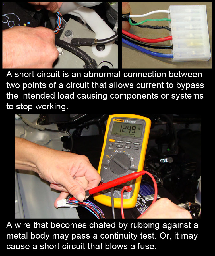
Symptoms of a short circuit may be: lights dimming, or even wires getting warm. When there is a short circuit, the flow of electricity is ‘shortened’ somewhere in the circuit. This will typically ‘blow’ a fuse, since the fuse is designed to protect the circuit. High current flow to ground causes fuses to blow. A short circuit can allow current to bypass the intended ‘load’ (the component the circuit is designed to operate). In a worst case scenario, it can cause damage to an electrical circuit. This is known as ‘short to ground’.
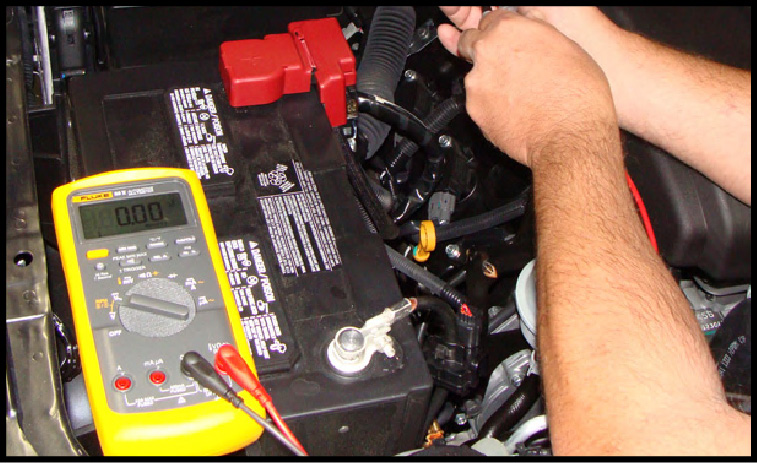
Using the Voltmeter
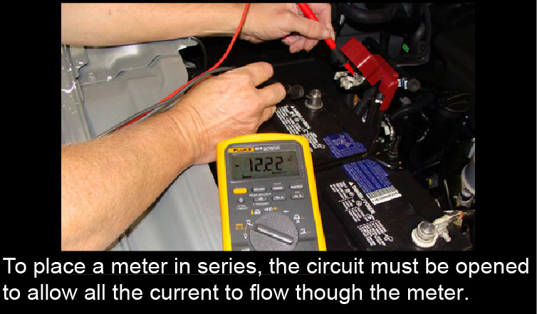
‘Series’ VOM Connection:
A voltmeter can be used to test for power to a load (headlights, etc.) by connecting it in series with a portion of the circuit power and the battery ground. A meter reading equal to battery voltage indicates continuity. This is a good first step while troubleshooting.
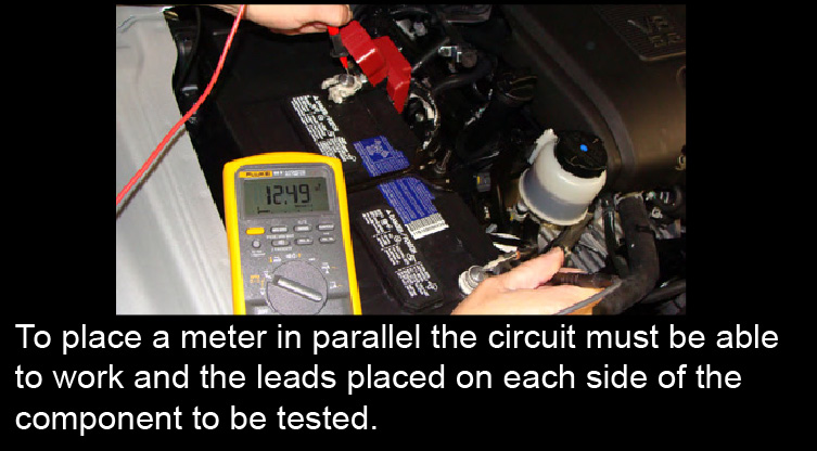
‘Parallel’ VOM Connection:
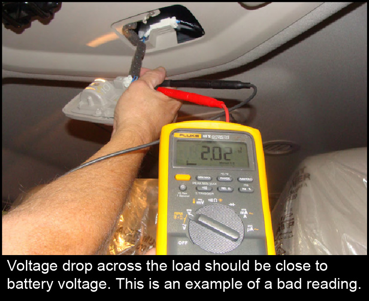
A voltmeter may be connected in parallel or ‘across’ various parts of a suspect component or circuit. Voltage drop is a way of identifying or checking for the amount of voltage (or loss) of that part of a circuit.
This method is better than just “checking for continuity (resistance)” because it tests the circuit under load while it is working.
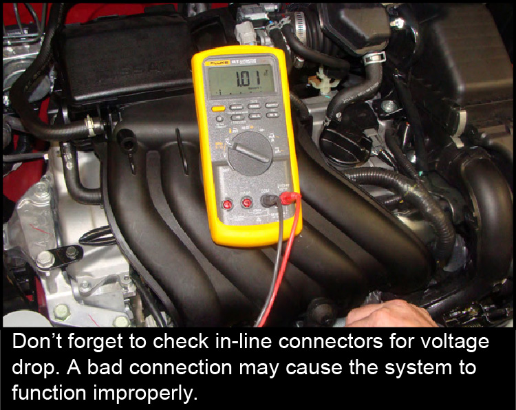
You should always check connectors that are part of the circuit you’re working with, just to make sure they are clean and snapped together properly. If a light is dim, start with the simplest check: the bulb. While you are at it, don’t overlook potential errors from past repairs. It’s possible the bulb is good, but the wrong bulb was installed previously. With a simple electrical meter check, a circuit under load can be easily tested for any unwanted restriction by using the Voltage Drop Test. Voltage drop is a way of identifying or checking for the amount of voltage used in a circuit. Remember, one volt is the amount of electrical pressure needed to move one amp of current through one ohm of resistance.
Voltage Drop Test
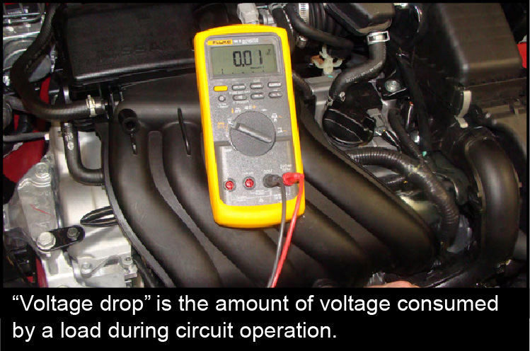
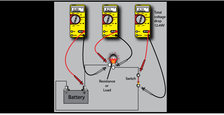
The meaning of “voltage drop” is the amount of voltage consumed by a load during circuit operation. The total of all voltage drops in a circuit equals the available voltage. When testing for voltage drop, the source voltage must be verified before taking voltage drop readings. A voltage drop test is performed when there is current in the circuit. In other words, the circuit must be activated or turned ON with current flowing. A voltmeter is used to measure the potential difference between two points. A voltage drop is the difference in measured voltage between any two different locations on a complete circuit while a load is being operated. A voltage drop measurement is done by measuring the voltage before entering a load and the voltage as it leaves the load. A circuit’s wiring and connections should have little or no resistance and all voltage should be used through the load. The “load” is any device using the power, such as lighting, a starter motor, window motors, horns, fuel injectors, etc. Measure after a load and the available voltage is lower than before the load.
Voltage drop testing provides a method for determining the amount of voltage that is being used by a wire or a component during system operation. Remember, poor connections, loose terminals, crimps, and/or connection corrosion issues may be the reason why a device is not operating properly. Any resistance in the circuit reduces electrical pressure. These conditions may not be found when measuring voltage, unless the circuit’s correct load is applied i.e., headlight turned on, etc.
Voltage drop tests are used to find components or circuits which have excessive resistance. The VOM’s positive lead should be connected to the circuit in the direction of the power source and negative lead toward the ground.
When you place your voltmeter “across”, or connected in parallel with the circuit you are testing, you are providing another path for the voltage to travel. The positive lead should be connected to the circuit in the direction of the power source and negative lead toward the ground. Operate or turn ON the circuit. Voltage will always follow the path of least resistance. So, if there is excessive resistance in the circuit you’re testing, then your meter becomes ‘the path of least resistance’ and will give a voltage reading.
When testing circuits, you’ll often need to find the voltages at various points. A voltage drop can occur in any part of a circuit when the circuit operates. Depending on the resistance, each load will have a different voltage drop The meter can indicate the amount of voltage being used by that portion of the circuit you’re testing. When checking voltage drop on a load, the load uses most of the available voltage. If resistance occurs in the circuit, less voltage is available for the load to operate. If the circuit is functioning properly, all voltage will pass directly to the load and your meter will register an acceptable reading.
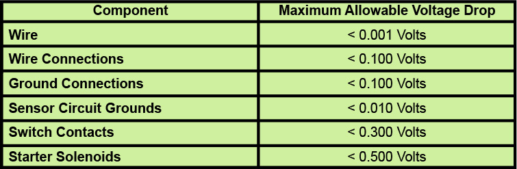
Voltage drop is the amount of electrical pressure lost or consumed as the voltage pushes through a load or resistance. An acceptable reading for most circuits other than fuel management systems (injectors, sensors, etc.) is less than 0.400 volts, although 0.100 volts or less is preferred. Some starter circuits can allow up to 0.500 volts during a voltage drop test. Anything higher than these values indicates a need for repair. Whenever a fault is suspected, both sides of the circuit should be tested. Because a circuit requires source, load, and ground, always inspect the ground side of the circuit. A possible repair in this instance usually includes cleaning corrosion from connections, repairing faulty terminal crimps, tightening fasteners and connectors, or providing sufficient ground for a component.
Voltage Drops — Good or Bad?
Voltage drop tests are usually performed when a load fails to operate properly. By this, it may be assumed a voltage drop is not good. But, voltage drops can be good or bad; it all depends on where they occur.
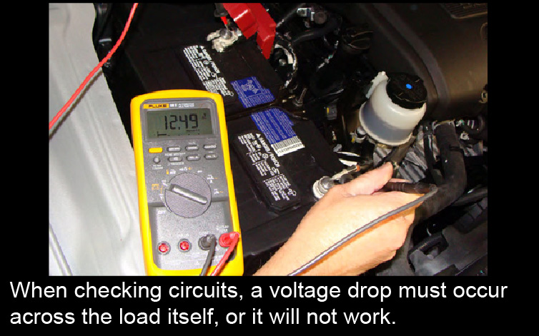
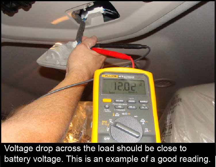
Good voltage drops are essential. Loads won’t work without them. Available voltage must be dropped across the load, or it cannot work.
High voltage drops will allow available voltage to be “dropped” at a high resistance elsewhere in the circuit; this steals electrical energy from the load. A high voltage drop in a circuit converts electrical energy into heat.
Everything has Resistance
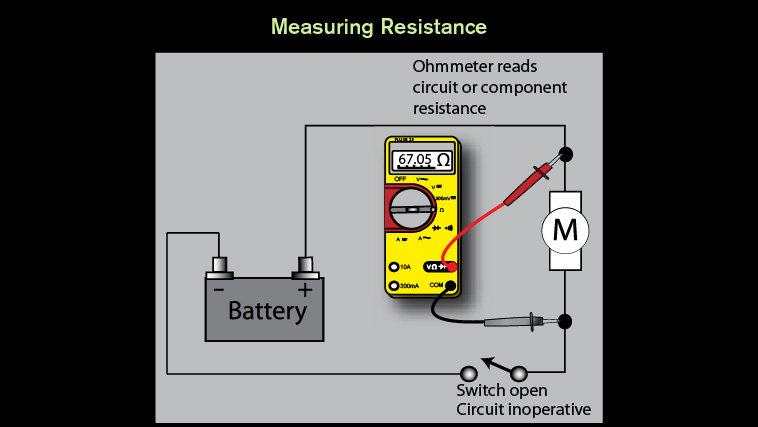
Understand that resistance and continuity are opposites. The multimeter measures resistance in ohms; it cannot measure continuity. When there is little resistance there is a great deal of continuity. So, when there is a great deal of resistance, there is little continuity. One important measurement that can be made with a multimeter is a resistance measurement. Wires, connectors, and switch contacts that make up a circuit all have some resistance. In a normally operating circuit, normal resistance is small enough that it doesn’t keep the load from operating properly. If you try to measure the resistance of a component in an operating circuit you will obtain false readings and you may damage the multimeter. Disconnect the component, and then measure the resistance. Unwanted or excessive resistance in the circuit reduces the amount of available electrical energy delivered to the load. The ohmmeter function on a digital multimeter is powered by an internal battery. It is used to apply a small voltage to a circuit or component and measure how much current flows through it, and then display the results as resistance.
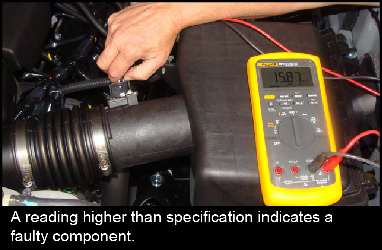
In the picture above, a reading higher than specification indicates a faulty component. If a circuit has excessive resistance, it prevents the wire or component from carrying sufficient current under high load conditions. Resistance can be caused by corrosion, loose wiring pins, pitted relay contacts, and other types of physical damage. These conditions may result in fixed or even variable resistance measurements. Excessive voltage drop caused by high resistance can be identified by inoperative component conditions, slower than normal electrical motor speeds, or even dim or intermittent flickering lamps.
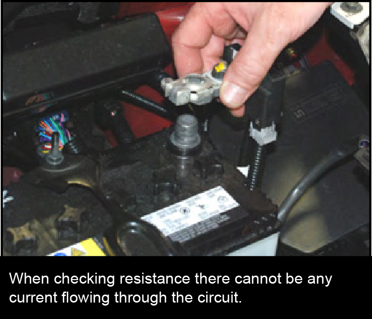
To measure the resistance of a component it must not be connected in a circuit. If you try to measure resistance of a component in a circuit you will obtain false readings (even if the power source is disconnected) and you may damage the multimeter. Disconnect the component, and then measure the resistance.
When checking resistance, it’s good to know what is the resistance value of the component you’re testing should be. Ideally, the voltage dropped across the load should be the same as the voltage available at the load. If this is the case, the voltage drop is a good one. Voltage dropped at the load will often be lower than available voltage. This is not a problem, as long as enough voltage is dropped to be able to operate the load. If voltage dropped across the load is a lot lower than available voltage, then the load won’t work properly. This indicates there is an excessive voltage drop somewhere in the circuit denying the load the power it needs.
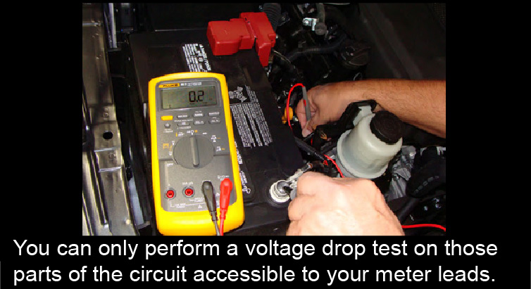
Is it Always Practical to Test Right at the Load?
No, you may not always be able to have direct access to the load. For instance, you cannot connect your meter leads across the terminals of an in-tank fuel pump. You can only perform a voltage drop test on those parts of the circuit accessible to your meter leads. Testing switches or relays is another common use of resistance testing. When the source voltage for a component is low due to a faulty switch, you should review each of the possible faults using a voltage drop test. When testing a switch, use a voltage drop test. A voltage drop across a switch should never exceed 0.300 volts (300mV).
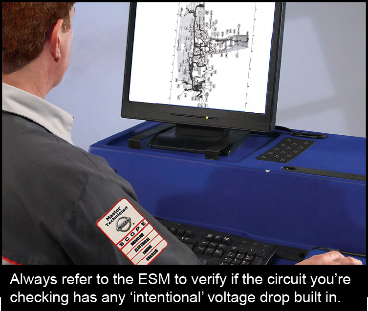
Always Check the ESM
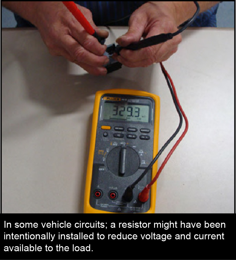
In some vehicle circuits, a resistor might have been intentionally installed to reduce voltage and current available to the load. Examples include the rheostat that dims the dash lights, ballast resistors in some fuel injector circuits, and motor resistors used to limit blower fan and electric fuel pump speeds. Be sure you know your circuit and identify any “intentional” voltage drop by checking the circuit design construction in a wiring diagram in the ESM.
Fall 2011 Copyright© 2011 by Nissan North America, Inc.