Distance Sensor Target Board Placement
Accurate adjustment of the radar alignment requires that the distance sensor target board be accurately positioned.
![]()
If the radar alignment is adjusted with the distance sensor target board in the incorrect position, the distance system will not function properly or the alignment procedure may not be completed successfully.
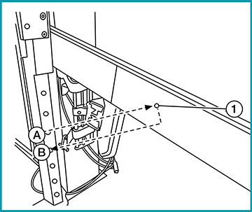
1. With the distance sensor target board arm extended, the laser beam (1) emitted by the laser assembly (A) will be reflected back (B) toward the laser assembly.
2. Rotate the distance sensor target board to achieve the necessary horizontal adjustment.
3. Adjust the distance sensor target board leveling screws to achieve the necessary vertical adjustment.
4. The figure shown illustrates the laser beam (A) emitted by the laser assembly (1) and its reflection (B) off the distance sensor target board arm.
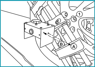
NOTE: When adjusted properly, the reflected laser beam (B) must align with the emitted laser beam (A) so the two laser beams will be seen as one.
When performing a Distance Sensor Alignment on the 2014 Rogue (T32), use the corrected specification (L) for positioning the target board.
NOTE: DO NOT place anything other than the distance sensor target board in the space shown in front of the vehicle (view from top).
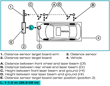
NOTE: The specification in the Electronic Service Manual (ESM), Section DAS – Driver Assistance Systems, for positioning the Distance Sensor Target Board is incorrect. Use the corrected specification (L) listed above.
Target Board Placement for Rear View Camera Calibration
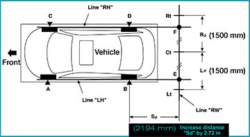
When performing a Rear View Camera Calibration on the 2014 Rogue (T32), use the corrected specification (Sd) for positioning the target boards.
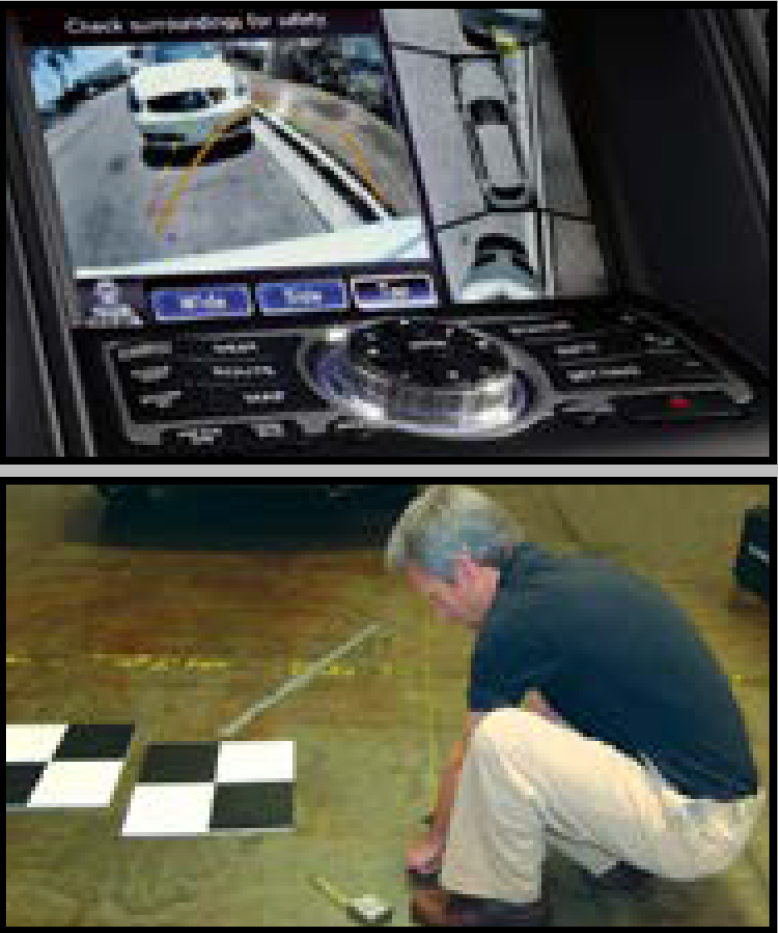
1. Confirm that target boards are oriented correctly.
2. Move all 3 target boards back an additional 2.72 in.
(New distance will be 2194 mm (86.38 in)
The specification in the Electronic Service Manual (ESM), Section DAS – Driver Assistance Systems, for positioning the Rear View Camera Targets is incorrect. Use the corrected measurement specification (Sd) listed in this article.
If CONSULT displays “Not completed”
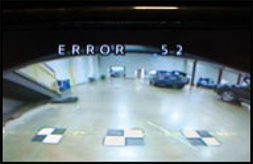
Enter the vehicle and look for an ERROR CODE displayed on the vehicle’s Rear View Monitor. This internal unit code will help you to determine what may have prevented the calibration from completing. The ERROR Codes only display for about 5 seconds. Touching the “Retry” button on CONSULT will retry the system aiming again, and if it is still not complete, the ERROR CODE will again display on the Rear View Monitor.
Rear View Camera error code 52 may be displayed on the Audio screen (Error 52: Pitch angle error). This indicates that the camera was not installed correctly or the location for the center target marker position vertical axis is NG.