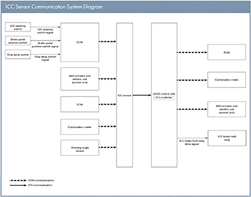
The 2015 Murano® has an ICC sensor that detects radar reflected from a vehicle ahead by irradiating radar forward and calculates a distance from the vehicle ahead and a relative speed based on the detected signal. The ICC sensor is installed on the front of the bumper and detects a vehicle ahead by using millimeter waves. The ICC sensor transmits information for Intelligent Cruise Control from the vehicle to the ADAS control unit via ITS communication.
For vehicles equipped with the Intelligent Cruise Control ICC Sensor Communication System Diagram (ICC) system, the ICC sensor must be aligned when the rear toe has been adjusted during a wheel alignment. The ICC sensor will also require alignment whenever the ICC sensor is removed and reinstalled and whenever front end structural repairs are performed. ICC sensor alignment consists of performing the mechanical vertical alignment (ICC sensor initial vertical alignment) described in the following procedure, followed by the electronic horizontal alignment (ICC sensor alignment) that is performed using C-III plus and the appropriate special service tools.
The use of a small level or angle meter is necessary to perform the ICC sensor initial vertical alignment.
Preparation for ICC Sensor Initial Vertical Alignment Procedure
1. Verify correct vehicle suspension height.
2. Repair or replace any damaged body components.
3. Verify proper tire inflation pressures.
4. Remove any accumulations of mud, snow or ice from the vehicle underbody.
5. Verify that there is no load in the vehicle (cargo or passenger).
6. Place the vehicle on a known-level horizontal surface such as a wheel or frame alignment rack to achieve satisfactory sensor vertical alignment results.
ICC Sensor Initial Vertical Alignment
NOTE: The ICC sensor initial vertical alignment procedure must be performed any time the distance sensor is removed or replaced.
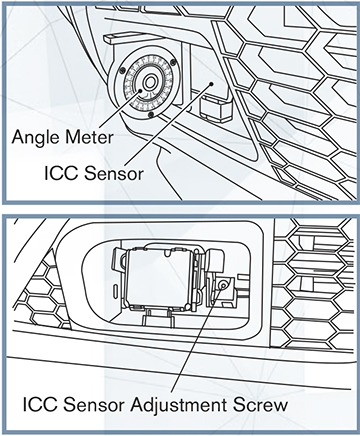
1. The ICC sensor is located near the right front headlamp in the front bumper fascia.
2. Place the small level or angle meter against the face of the ICC sensor.
3. Turn the ICC sensor adjustment screw to level the sensor.
4. Make sure the ICC sensor electrical connector located on the bottom of the sensor is connected.
5. Perform the ICC sensor alignment procedure.
ICC Sensor Alignment Overview
Check and set the position of the IC C target board then proceed with the ICC sensor alignment procedure using the ICC alignment kit (per the ESM).
1. Set C-III plus to the ICC Sensor Alignment Mode
2. Perform ICC Sensor Alignment
• Adjust the ICC sensor alignment in a vertical direction with C-III plus per the required steps.
• The ICC sensor alignment in the horizontal direction is performed automatically and cannot be adjusted manually.
3. Perform ICC Sensor Alignment Confirmation
4. Perform Action Test