The Simple Circuit
Understanding basic automotive electrical operation is essential to your basic skills and helps your ability to diagnose root causes and repair electrical conditions. The following information will help you review the elements of electricity, identify techniques for understanding circuits, resistance, load, check open circuit voltage or available voltage, and voltage drop.
Remember the three elements of electricity; voltage, amperage, and resistance. Voltage (sometimes referred to as electromotive force) is the representation of the electric potential energy between two points in an electric circuit, expressed in volts. Think of voltage as the electrical pressure that exists between two points in a conductor, or the force that causes the electrons to move in an electrical circuit. In other words, it’s the pressure or force that makes electrons move in a certain direction within a conductor. As electrons move from a negatively charged area to the positively charged area, this movement of electrons between atoms is called electrical current. Electrical current is the measure of the flow of these electrons through a conductor or the electricity flowing in a circuit or an electrical system. If you think of a garden hose as an example, current is the amount of water flowing through the hose. Voltage is the amount of pressure forcing the water through the hose.
This flow of electrons is measured in units called amperes. Amperes or an amp is the unit measure of the strength or rate of flow of electrical current. Electrical resistance describes the amount of opposition there is to the flow of current. The larger the resistance value, the more it fights. Anything that impedes or stops the flow of current raises the circuit resistance. This resistance or opposition of current is measured in Ohms. One volt is the amount of pressure needed to move one amp of current through one ohm of resistance in a circuit.
AN ELECTRICAL CIRCUIT
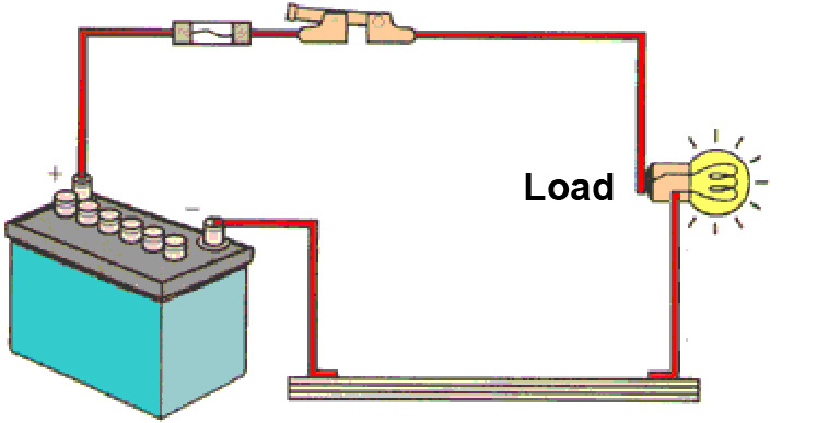
A circuit is a complete path along which electricity flows. The essential elements in a basic electrical circuit consist of: A source, load, and ground. Electricity cannot flow without a power source (battery), and a load (bulb or resistor-electrical device/ component) and a closed conductive path (wires connecting it). Electrical circuits consist of wires, wire connectors, switches, circuit protection devices, relays, electrical loads, and grounds. The circuit shown below has a power source, fuse, switch, a lamp and wires connecting each into a loop. When the connection is complete, current flows from the positive terminal of the battery through the circuit to the negative terminal of the battery.
In a complete circuit, the source voltage supplies the electrical pressure that pushes the current through the circuit. The source side of the circuit includes all parts of the circuit between the positive side battery post and the load. The load is any device in the circuit that produces light, heat, sound or electrical movement when current is flowing. A load always has resistance and consumes voltage only when current is flowing. In the example below, one end of the wire from the second lamp returns current to the battery since it is connected to the vehicle body or frame. The body or frame works as the body ground (meaning that part of the circuit that returns the current to the battery).
CIRCUIT REQUIREMENTS
A complete electrical circuit is required in order to make electricity practical. Electrons must flow from and return to the power source. By connecting the negative and positively charged ends of a power source to a conductor, we have the potential of electron movement. So a complete circuit is a ‘path’ or loop that will allow electricity (Current) to flow through. But to make this loop or circuit do work for us, we need to add two things: A power Source (battery or alternator) and a Load (Example—headlights). After the electricity has done its work through the Load, it needs to return back to the Source (Battery). If you have a break in this circuit somewhere, you’ll have a break in the electrical flow. This is also known as an ‘open’ circuit. Open circuit voltage is measured when there is no current flow through the circuit.
Types of Circuits
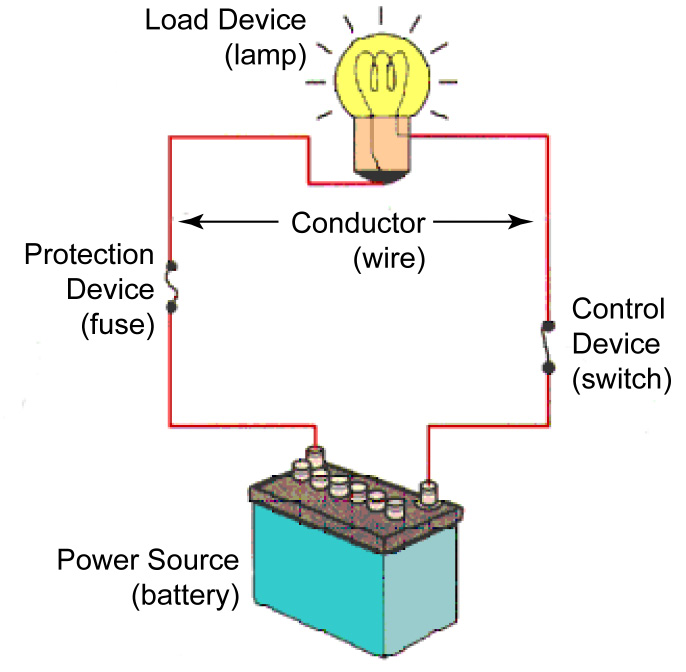
There are three basic types of circuits: Series, Parallel, and Series-Parallel. Individual electrical circuits normally combine one or more resistance or load devices. The design of the automotive electrical circuit will determine which type of circuit is used but they all require the same basic components to operate properly:
1. Power Source (Battery, Alternator, Generator, etc.) is needed to supply the flow of electrons (electricity).
2. Protection Device (Fuse, Fusible Link, or Circuit Breaker) prevents damage to the circuit in the event of a short.
3. Control Device (Switch, Relay, or Transistor) allows the user control to turn the circuit on or off
4. Load Device (Lamp, Motor, Winding, Resistor, etc) .converts the electricity into work.
5. Conductor (a return path, wiring to Ground) provide an electrical path to and from the power source.
Series Circuits
The components of a series circuit are connected end to end one after another to make a simple loop for current to flow through the circuit. A Series Circuit has only one path to ground, all loads are placed in series, so current must go through each component to get back to ground. If there is a break in the circuit (such as a blown light bulb) the whole circuit and any other bulbs go out. If the path is broken, no current flows and no part of the circuit works. Christmas tree lights are a good example; when one light goes out the entire string stops working.
_opt.jpeg)
Parallel Circuits
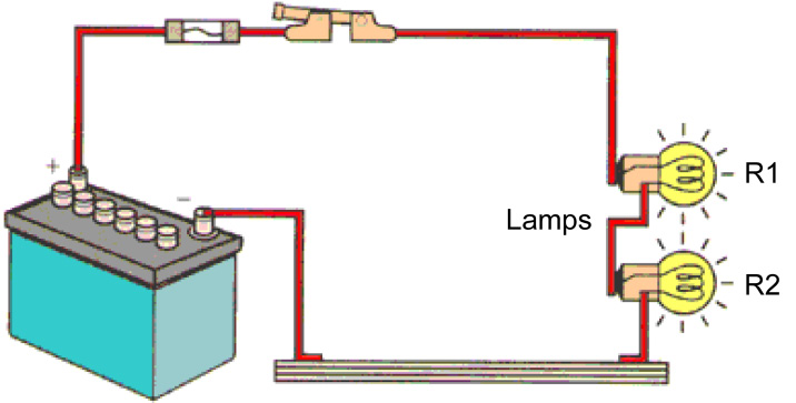
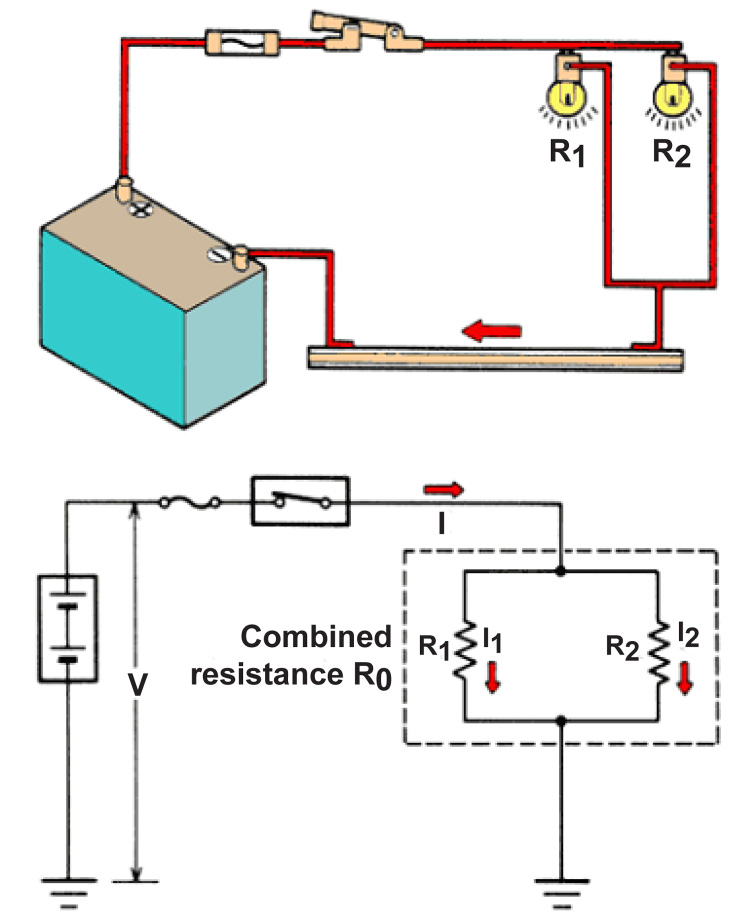
A parallel circuit has more than one path for current flow. The same voltage is applied across each branch. If the load resistance in each branch is the same, the current in each branch will be the same. If the load resistance in each branch is different, the current in each branch will be different. The components of a parallel circuit are connected side by side so the current flow has a choice of paths in the circuit. If one branch is broken, current will continue flowing to the other branches.
In the parallel circuit below, two or more resistances (R1, R2, etc.) are connected in a circuit as follows: one end of each resistance is connected to the positive side of the circuit, and one end is connected to the negative side.
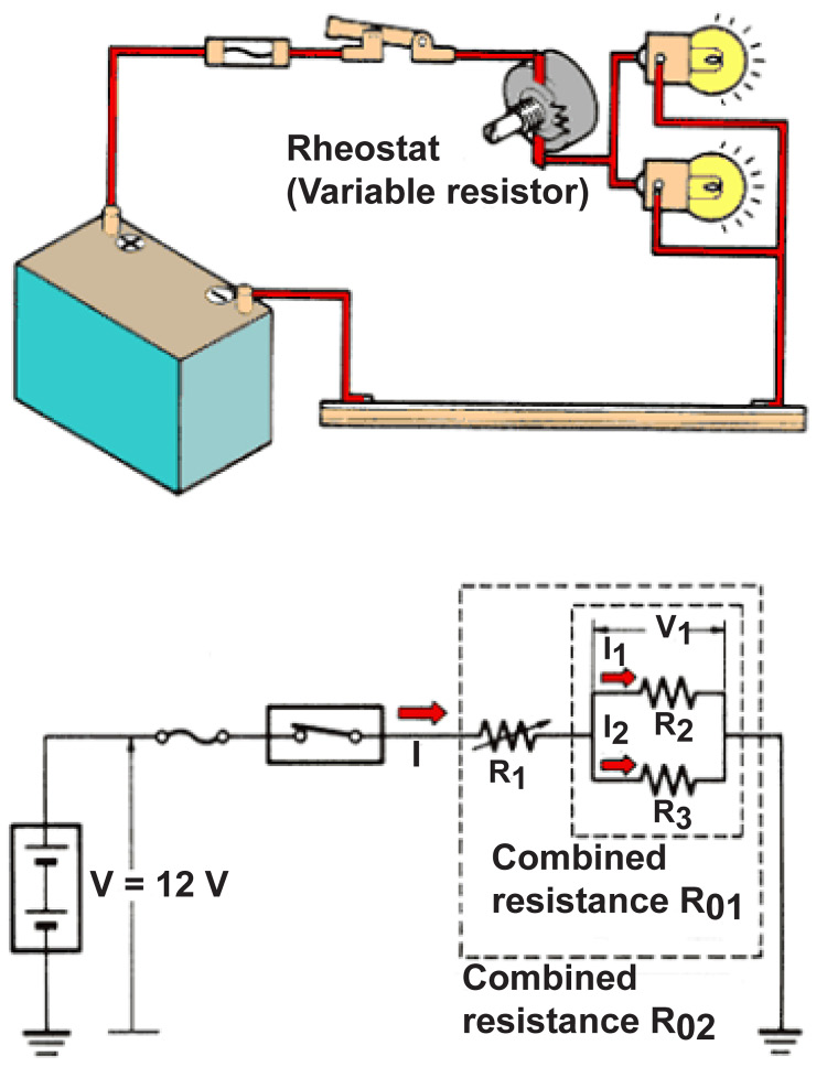
Series-Parallel Circuits
A series-parallel circuit has some components in series and others in parallel. The power source and control or protection devices are usually in series; the loads are usually in parallel. If the series portion is broken, current stops flowing in the entire circuit. If a parallel branch is broken, current continues flowing in the series portion and the remaining branches.
Interior dash lights are a good example of a resistance and lamps connected in a series-parallel circuit. In this example, by adjusting the rheostat, you can increase or decrease the brilliance of the lights.
Diagnosing Circuits
Electrical circuit issues are usually caused by a failed component or low or high resistance in a circuit.
Low resistance in a circuit may generally be caused by a shorted component, or a short to ground, and will generally cause a fuse, fusible link or circuit breaker to blow.
High resistance in a circuit can be caused by corrosion or an open in the source side or the ground side of a circuit. Anything that impedes or stops the flow of current raises the circuit resistance.
CIRCUIT PROTECTION DEVICES
Circuit protection devices are used to protect wires and connectors from being damaged by excess current flow caused by either an over current or short-circuit. Excess current causes excess heat, which may cause a circuit protection to “open circuit”. Fuses, fuse elements, fusible links, and circuit breakers are used as circuit protection devices. Circuit protection devices are available in a variety of types, shapes, and specific current ratings.
Fuses
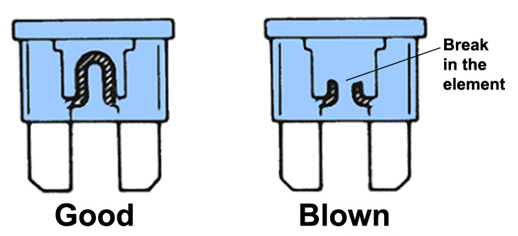
A fuse is the most common type of overcurrent protection device. A fuse is placed in an electrical circuit and receives the same electric supply as the protected circuit. A short or ground condition allows current to flow to ground before it reaches the load. So when too much current flow is supplied exceeding the rating of the fuse, it “blows” or “blows out”, because the metal wire or fuse element in the fuse melts. This opens or interrupts the circuit and preventing wires and connectors and electronic components of the circuit from being damaged by the over current. The size of the metal fuse element (or fuse link) determines its rating.
Remember, excessive current causes excess heat, and it’s the heat and not the current that causes the circuit protector to open. Once a fuse “blows” it must be replaced with a new one. Once you’ve determined that a fuse is blown, the most critical element is ensuring that you replace the fuse with the exact same amperage rating as the blown one. The maximum load to a single fuse is designed to never exceed seventy percent of the fuse’s rating. A fuse should normally be selected with a rating just over the normal operating current (amperage) which can be used at any voltage below the fuse voltage rating. If the new fuse blows too, then there is something wrong with the circuit. Check the wiring to the components that run off the blown fuse. Look for bad connections, cuts, breaks or shorts.
Fuses have different time-current load characteristics for finite operating time in use, and for the speed at which a fuse element blows in response to an overcurrent condition. Over time normal surges may tend to cause fatigue to fuse wires, which can result in a fuse blowing even when there isn’t a fault condition. Fuses are always marked with the Rated Current in Amperes they’re designed to carry on a continuous basis at a standard temperature.
Fuse Locations
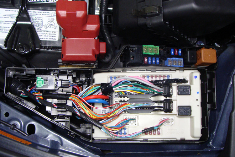
Fuses are located throughout the entire vehicle. Common locations include the engine compartment, under the dashboard behind the left or right kick panels, or under the IPDM. Fuses are usually grouped together and are often mixed in with other components like relays, circuit breakers, and fuse elements.
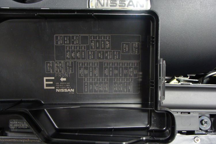
Fuse Block Covers
Fuse / relay block covers usually label the location and position of each fuse, relay, and fuse element contained within.
Fuse Types
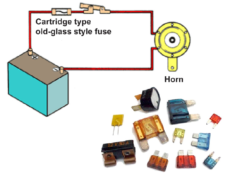
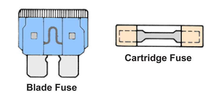
Fuses are classified into basic categories: blade type fuses and old-glass style cartridge fuses. Several variations of each are used.
Common Fuse Types
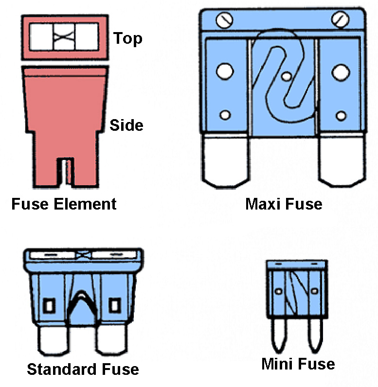
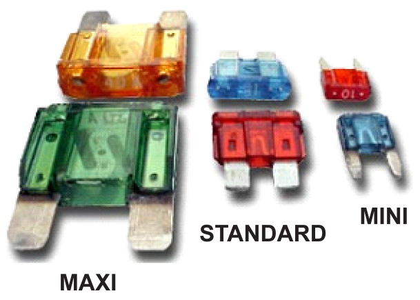
The blade fuse and fuse element are by far the most commonly used today. Blade type fuses have a plastic body and two prongs that fit into sockets and can be mounted in fuse blocks, in-line fuse holders, or fuse clips. Three different types of blade fuses exist; the Maxi Fuse, the Standard Auto fuse, and the Mini fuse.
Basic Construction
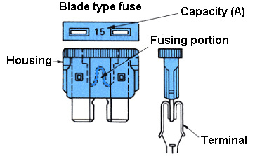
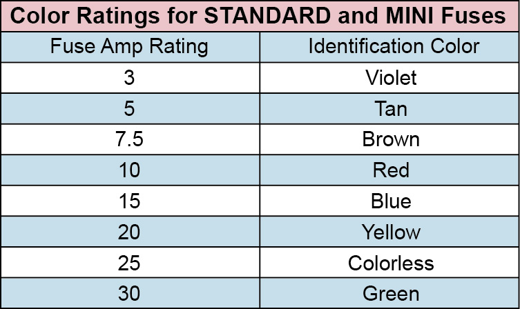
The blade type fuse is a compact design with a metal element and transparent insulating housing which is color-coded for each current rating. (Standard Auto shown below; however construction of both the Mini and Maxi fuses are the same.)
Fuse Amperage Color Rating
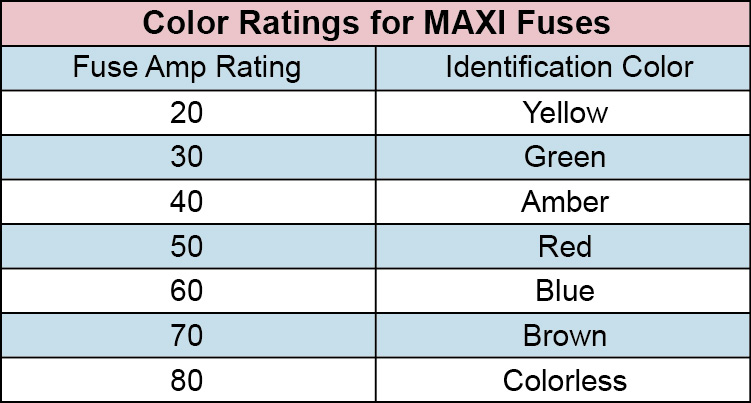
Fuse amperage color ratings for both the Mini and standard Auto fuses are identical. However, the amperage color ratings of maxi fuses use a different color coding scheme.
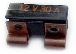
Fusible Links And Fuse Elements
Fusible links are divided into two categories: the fuse element cartridge and the fusible link. The construction and function of fusible links and fuse elements are similar to that of a fuse. The main difference is that the fusible link and fuse element are used to protect higher amperage electrical circuits, generally circuits 30 amps or more. As with fuses, once a fusible link or fuse element blows out, it must be replaced with a new one. Fusible links protect circuits between the battery and the fuse block.
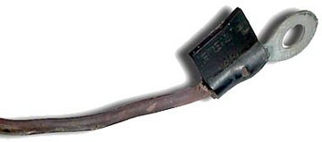
Fusible Links
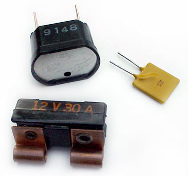
Fusible links are short pieces of a smaller diameter wire designed to melt during an over current condition. A fusible link is usually four (4) wire sizes smaller than the circuit that it is protecting. The insulation of a fusible link is a special nonflammable material. This allows the wire to melt, but the insulation to remain intact for safety. Some fusible links have a tag at one end that indicates its rating. Like fuses, fusible links must be replaced after they have “blown” or melted opened. Many manufacturers have replaced fusible links with fuse elements or Maxi fuses.
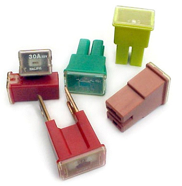
Fuse Element Cartridge
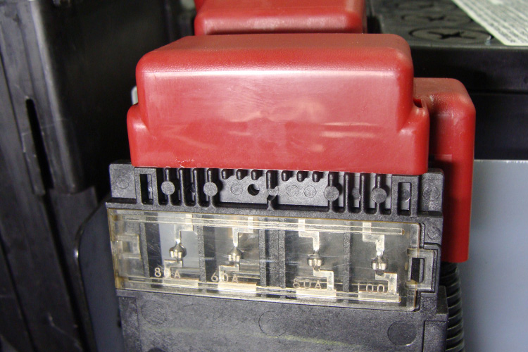
Fuse elements, a cartridge type fusible link, are also known as a Pacific fuses. The element has the terminal and fusing portion as a unit. Fuse elements have all but replaced the fusible link. They consist of a housing that contains both the terminal and fuse. Fuse element cartridges are color coded for each current amperage. Although fuse elements are available in two physical sizes and are either plug in or bolt on design, the plug-in type is the most popular.
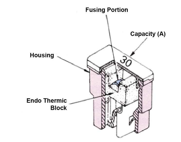
Fuse Element Cartridge Construction
Construction of the fuse element is quite simple. A colored plastic housing contains the fusing portion element which can be viewed through a clear top. Fuse ratings are also stamped on the case.
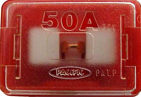
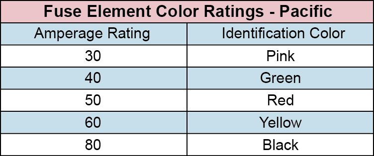
Fuse Element Color Identification
Fuse amperage color ratings are shown below. The fusing portion of the fuse element is visible through a clear window. The amperage ratings are also listed on the fuse element.
Fusible Elements
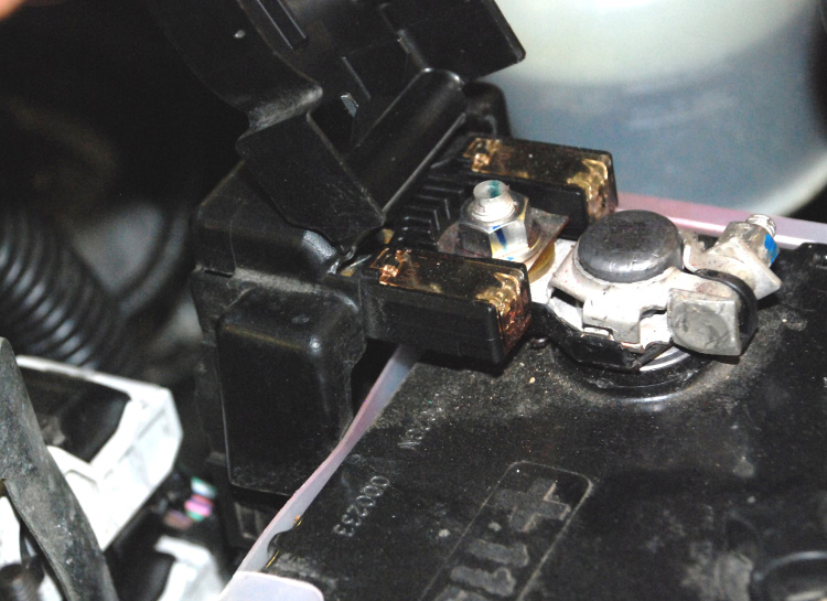
Fusible elements are often located near the battery by themselves.
Fusible elements can also be located in relay/ fuse boxes in the engine compartment.
Circuit Breakers
Circuit breakers are used in place of fuses for the protection of complicated power circuits such as the power windows, sunroofs and heater circuits. Three types of circuit breakers exists: The manual reset type - mechanical, the automatic resetting type - mechanical, and the automatically reset solid state type - PTC. Circuit breakers are usually located in relay/fuse boxes; however, some components like power window motors have circuit breakers built in.
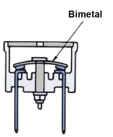
Circuit Breaker Construction (Manual Type)
A circuit breaker basically consists of a bimetal strip connected to two terminals and to a contact in between. Manual circuit breaker when tripped (current flow beyond its rating) will open and must be reset manually. These manual circuit breakers are called “non-cycling” circuit breakers.
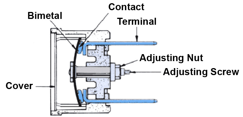
Circuit Breaker Operation (Manual Type)
The circuit breaker contains a metal strip made of two different metals bonded together called a bimetal strip. This strip is in the shape of a disc and is concaved downward. When heat from the excessive current is higher than the circuit breaker current rating, the two metals change shape unevenly. The strip bends or warps upwards and the contacts open to stop current flow. The circuit breaker can be reset after it is tripped.
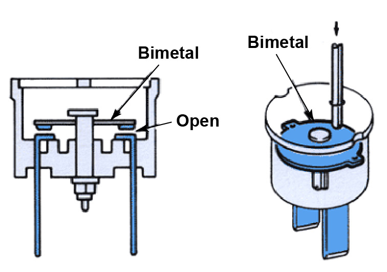
Manual Reset Type
When a circuit breaker is opened by an over-current condition, the circuit breaker requires reset. To do so, insert a small rod (paper clip) to reset the bimetal plate as shown.
Automatic Resetting Type – Mechanical
Circuit breakers that automatically reset are called “cycling” circuit breakers. This type of circuit breaker is used to protect high current circuits, such as power door locks, power windows, air conditioning, etc. The automatically resetting circuit breaker contains a bimetal strip. The bimetal strip will overheat and open from the excess current by an overcurrent condition and is automatically reset when the temperature of the bimetal strip cools.
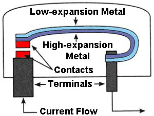
Auto Reset Construction And Operation
A cycling circuit breaker contains a metal strip made of two different metals bonded together called a bimetal strip. When heat from the excessive current is higher than the circuit breaker current rating the two metals change shape unevenly. The strip bends upwards and a set of contacts open to stop current flow. With no current flowing the bimetal strip cools and returns to its normal shape, closing the contacts, and resuming the current flow. Automatically resetting circuit breakers are said to “cycle” because they cycle open and closed until the current returns to a normal level.
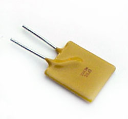
Automatic Resetting Solid State Type – PTC
A polymer Positive Temperature Coefficient (PTC) device is known as a resettable fuse.
A Polymer PTC is a special type of circuit breaker called a thermistor (or thermal resistor). A PTC thermistor increases resistance as its temperature is increased. PTCs, which are made from a conductive polymer, are a solid state device, which means they have no moving parts. PTCs are commonly used to protect power window and power door lock circuits.
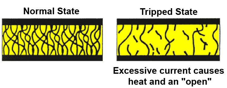
Polymer PTC Construction and Operation
In its normal state, the material in a polymer PTC is in the form of a dense crystal, with many carbon particles packed together. The carbon particles provide conductive pathways for current flow. This resistance is low. When the material is heated from excessive current, the polymer expands, pulling the carbon chains apart. In this expanded “tripped” state, there are few pathways for current. When current flow exceeds the trip threshold, the device remains in the “open circuit” state as long as voltage remains applied to the circuit. It resets only when voltage is removed and the polymer cools. PTCs are used to protect power window and power door lock circuits.
CONTROL DEVICES
Control devices are used to “turn on” or “turn off” current flow in an electrical circuit. Control devices include a variety of switches, relays, and solenoids. Electronic control devices include capacitors, diodes, and switching transistors. Switching transistors act as a electronically-controlled switch or relay. The advantage of a transistor is its speed in opening and closing a circuit.
Control devices are needed to start, stop, or redirect current flow in an electrical circuit. A control device or switch allows the electricity in a circuit to be turned ON or OFF. A switch is just a connection in the circuit that can be opened or closed. Most switches require physical movement for operation while relays and solenoids are operated with electromagnetism.
Switches
- Single Pole Single Throw (SPST)
- Single Pole Double Throw (SPDT)
- Multiple Pole Multiple Throw (MPMT or Gang Switch)
- Momentary Contact
- Mercury
- Temperature (Bi-metallic)
- Time Delay
- Flasher
- RELAYS
- SOLENOIDS
A switch is the most common circuit control device. Switches usually have two or more sets of contacts. Opening these contacts is called “break” or “open” the circuit, closing the contacts is called “make” or “completing” the circuit.
Switches are described by the number of Poles and Throws they have. “Poles” refer to the number of input circuit terminals while “Throws” refer to the number of output circuit terminal. Switches are referred to as SPST (single-pole, single-throw), SPDT (single-pole, double-throw), or MPMT (multiple-pole, multiple-throw).
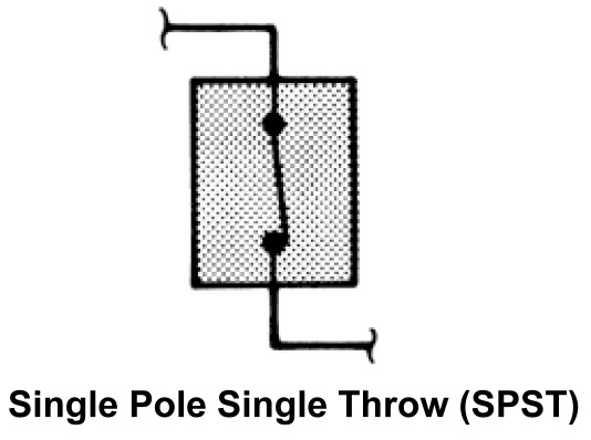
Single Pole Single Throw (SPST)
The simplest type of switch is a “hinged pawl” or “knife blade” switch. It either “completes” (turn ON) or “break” (turn OFF) the circuit in a single circuit. This switch has a single input pole and a single output throw.
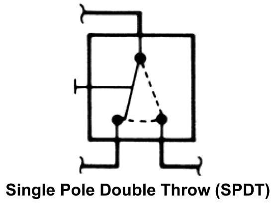
Single Pole Double Throw (SPDT)
A single-pole input, double-throw output switch has one wire going it and two wires coming out. A Headlamp dimmer switch is a good example of a single-pole double-throw switch. A Headlamp dimmer switch sends current to either the high-beams or low-beams of the headlight circuit.
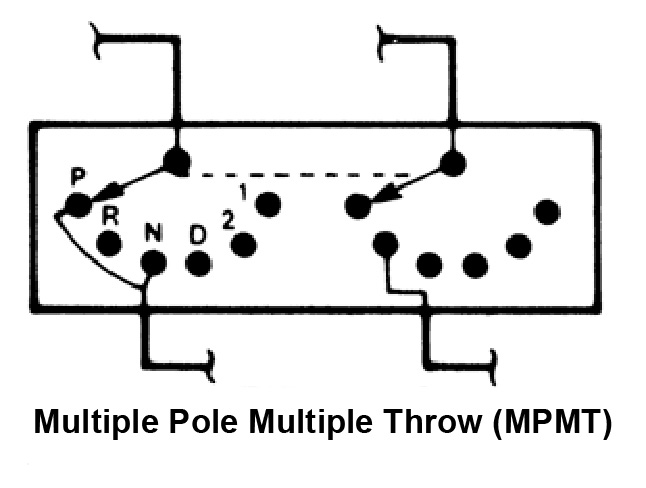
Multiple Pole Multiple Throw (MPMT)
Multiple-Pole input, Multiple-Throw output switches, which are also known as “gang” switches, have movable contacts in wired in parallel. These switches move together to supply different sets of output contacts with current. An ignition switch is a good example of a multiple-pole multiple-throw switch. Each switch sends current from different source to different output circuits at the same time depending on position. The dotted line between the switches indicates they move together; one will not move without the other moving as well.
Momentary Contact
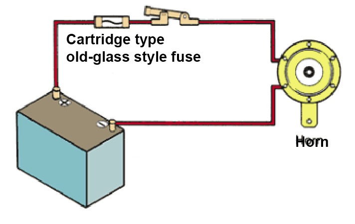
The momentary contact switch has a spring-loaded contact that keeps it from making the circuit except when pressure is applied to the button. This is a “normally open” type (shown below). A horn switch is a good example of a momentary contact switch. Push the horn button and the hold sounds; release the button and the horn stops.
_opt.jpeg)
A variation of this type is the normally closed (not shown) which works the opposite as described above. The spring holds the contacts closed except when the button is pressed. In other words the circuit is “ON” until the button is pushed to break the circuit.
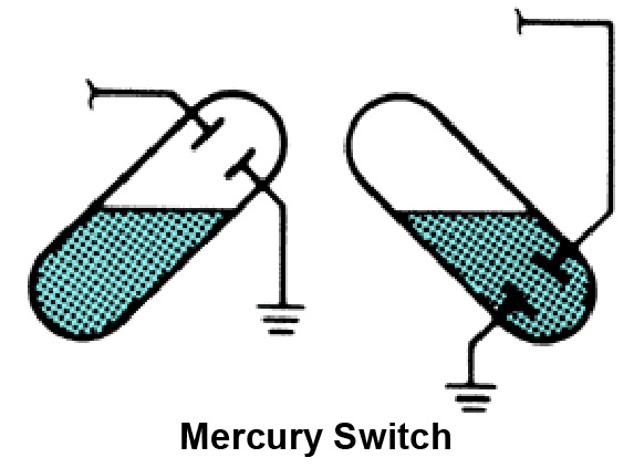
Mercury
A mercury switch is made of a sealed capsule that is partially filled with mercury. In one end of the capsule are two electrical contacts. As the switch is rotated (moved from true vertical) the mercury flows to the opposite end of the capsule with the contacts, completing the circuit. Mercury switches are often used to detect motion, such as the one used in the engine compartment on the light. Other uses include fuel cut off for roll-overs, and some air bag sensor applications. Mercury is a hazardous waste and should be handled with care.
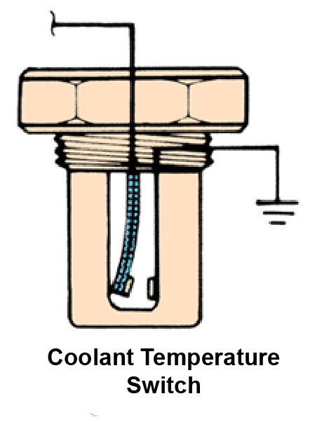
Temperature Bi-Metallic
A temperature-sensitive switch, also known as a “bi-metallic” switch, usually contains a bimetal element that bends when heated to make contact completing a circuit or to break contact opening a circuit. In an engine coolant temperature switch, when the coolant reaches the temperature limit, the bimetal element bends causing the contacts in the switch to close. This completes the circuit and lights the warning indicator on the instrument panel.
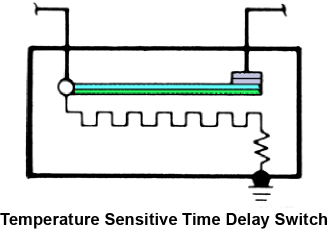
Time Delay
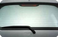
A time delay switch contains a bimetal strip, contacts, and a heating element. The time delay switch is normally closed. As current flows through the switch, current flows through the heating element causing it to heat, which causes the bimetal strip to bend and open the contacts. As current continues to flows through the heating element, the bimetal strip is kept hot, keeping the switch contacts open. The amount of time delay before the contacts open is determined by the characteristics of the bimetal strip and the amount of heat produced by the heating element. When power to the switch is turned off, the heating element cools and the bimetal strip returns to the rest position and the contacts are closed. A common application for a time delay switch is the rear window defroster.
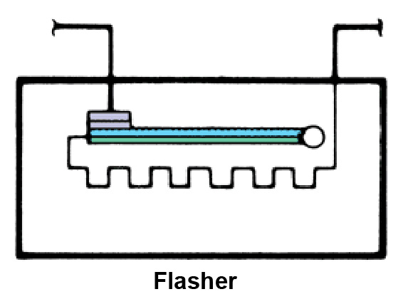
Flasher
A flasher operates basically the same as the time delay switch; except when the contacts open, current stops flowing through the heating element. This causes the heating element and bimetal strip to cool. The bimetal strip returns to the rest position which closes the contacts, allowing current to flow through the contacts and heating element again. This cycle repeats over and over until power to the flasher is eliminated. Common uses for this type of switch are the turn signals or the four-way flasher (hazard lamps).
Relays
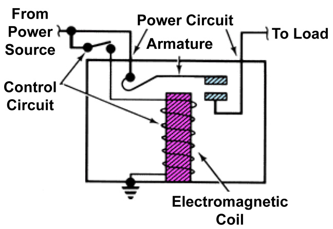
A relay is simply a remote-control switch, which uses a small amount of current to control a large amount of current. A typical relay has both a control circuit and a power circuit. Relay construction contains an iron core, electromagnetic coil, and an armature (moveable contact set). There are two types of relays: normally open (shown below) and normally closed (NOT shown). A Normally open (N.O.) relay has contacts that are “open” until the relay is energized while a normally closed (N.C.) relay has contacts that are “closed” until the relay is energized.
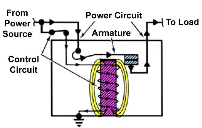
Relay Operation
Current flows through the control coil, which is wrapped around an iron core. The iron core intensifies the magnetic field. The magnetic field attracts the upper contact arm and pulls it down, closing the contacts and allowing power from the power source to go to the load. When the coil is not energized, the contacts are open, and no power goes to the load. When the control circuit switch is closed, however, current flows to the relay and energizes the coil. The resulting magnetic field pulls the armature down, closing the contacts and allowing power to the load. Many relays are used for controlling high current in one circuit with low current in another circuit. An example would be a computer, which controls a relay, and the relay controls a higher current circuit.
Solenoids - Pulling Type
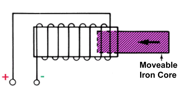
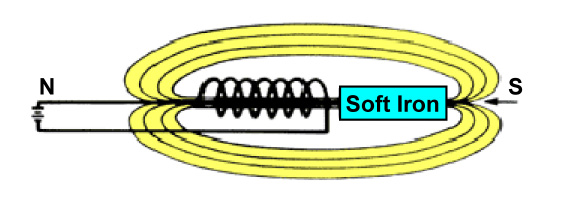
A solenoid is an electromagnetic switch that converts current flow into mechanical movement. As current flows through the winding a magnetic field is created. The magnetic field will pull the moveable iron core into the center of the winding. This type of solenoid is called a “pulling” type solenoid, as the magnetic field pulls the moveable iron core into the coil. A common use for pulling solenoids is in the starting system. The starter solenoid engages the starter with the flywheel.
Pulling Type Operation
As current flows through the winding a magnetic field is created. These magnetic lines of force want to be as small as possible. If an iron core is placed near the coil that has current flowing through it, the magnetic field will stretch out like a rubber band, reaching out and pulling the iron bar into the center of the coil.
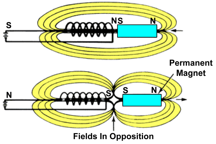
Push/Pull Type Operation
In a “push-pull” type solenoid, a permanent magnet is used for the core. Since “like” magnetic charges repel and “unlike” magnetic charges attract, by changing the direction of current flow through the coil, the core is either “pulled in” or “pushed out.” A common use for this type of solenoid is on electric door locks.
LOAD DEVICES
Any device such as a lamp, horn, wiper motor, or rear window defogger that consumes electricity is called a load. In an electrical circuit, all loads are regarded as resistance. Loads use up voltage and control the amount of current flowing in a circuit. Loads with high resistance cause less current to flow while those with lower resistance allow high current rates to flow.
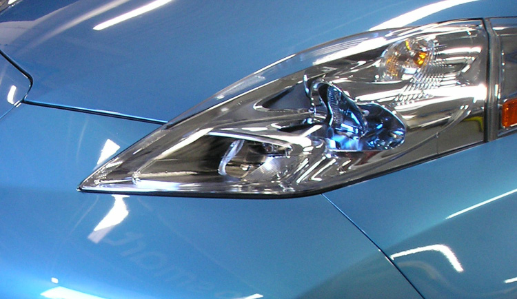
Lights
Lights come in different wattages to give off more or less light. When bulbs are wired in series they share the available voltage in the system and the light emitted is reduced. When the bulbs are placed in parallel each bulb has the same amount of voltage so the lights will be brighter.
Motors
Motors are used in various systems in a vehicle to include power seats, windshield wipers, cooling system, heating and air condition systems. The motors can be run at a single speed such as the power seats or a multiple speeds such as the heating and air conditioning blower motor. When motors are run at a single speed they are usually supplied system voltage. However when the motors are run at different speed the voltage input can be at different spots on the armature to reduce to increase the speed of the motor similar to the way windshield wiper motor is designed or they can share the voltage with a resistor that is in series with the motor like the blower motor for the heating and air conditioning system.
Heating elements
Heating elements can be found in the outside mirrors, rear glass and in the seats. Heating elements are normally supplied system voltage for a specific amount of time to heat the component when requested.
WHAT IS OHM’S LAW?
Understanding the relationship that exists between voltage, current, and resistance in electrical circuits is important for fast, accurate electrical problem diagnosis and repair. Ohm’s Law states: The current in a circuit will always be proportional to the applied voltage and inversely proportional to the amount of resistance present. This means that if the voltage goes up, the current flow will go up, and vice versa. Also, as the resistance goes up, the current goes down, and vice versa. Ohm’s Law can be put to good use in electrical troubleshooting. But calculating precise values for voltage, current, and resistance is not always practical ... nor, really needed. You do however need to be able to predict what should be occurring in a circuit, as opposed to what is occurring in an incident vehicle.
Source Voltage is not affected by either current or resistance. It is either too low, normal, or too high. If it is too low, current will be low. If it is normal, current will be high if resistance is low, or current will be low if resistance is high. If voltage is too high, current will be high.
Current is affected by either voltage or resistance. If the voltage is high or the resistance is low, current will be high. If the voltage is low or the resistance is high, current will be low. Current goes up as resistance goes down.
Resistance is not affected by either voltage or current. It is either too low, okay, or too high. If resistance is too low, current will be high at any voltage. If resistance is too high, current will be low if voltage is okay. The measure of resistance is how difficult it is to push the flow of electrical charge along.
Good resistance: To operate properly, some circuits require a “limit” to current flow. In this case, ‘resistors’ are used. Resistors are rated at different values depending on how much the current flow needs to be limited.
Bad resistance: In most cases, too much resistance reduces the current flow and may cause systems not to work properly. Dirt or corrosion at electrical connectors or at ground connections is usually the culprit.
Note: When the voltage stays the same, current goes up as resistance goes down, and current goes down as resistance goes up. Bypassed devices reduce resistance, causing high current. Loose connections increase resistance, causing low current flow.
Ohm’s Law Formula
When voltage is applied to an electrical circuit, current flows in the circuit. The following special relationship exists among the voltage, current and resistance within the circuit: the size of the current that flows in a circuit varies in proportion to the voltage which is applied to the circuit, and in inverse proportion to the resistance through which it must pass. This relationship is called Ohm’s law.
Ohm’s Law Symbol Shortcut
Mathematical formulas can be difficult for many who don’t use them regularly. Most people can remember a picture easier than a mathematical formula. By using the Ohms law symbol below, anyone can remember the correct formula to use. By knowing any two values you can figure out the third. Simply put your finger over the portion of the symbol you are trying to
figure out and you have your formula.
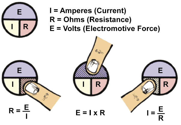
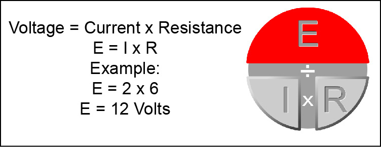
Figuring voltage
Voltage is the difference in electrical pressure or force that exists between the negative and positive sides of a circuit. Voltage causes current to flow. One volt (V) is the amount of electrical pressure needed to move one amp (A) of current through one ohm (Ω) of resistance.
To figure the amount of voltage in a circuit you need to know the current flowing in the circuit and the resistance of the circuit. Using ohms law, take the current times the resistance to get the voltage applied to the circuit. An example would be if you had 2 amps of current and 6 ohms of resistance you would multiply 2 amps of current times 6 ohms of resistance to get 12 volts.
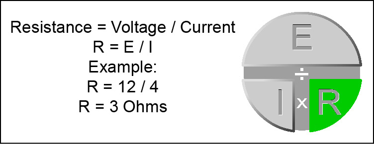
Figuring resistance
To find the resistance of a circuit you need to know the voltage applied to the circuit and the current flowing in the circuit. Once you have these two values you would take the voltage and divide it by the current. An example would be if you have 12 volts applied to the circuit with 4 amps of current flowing you would divide 12 volts by 4 amps to get 3 ohms of resistance.
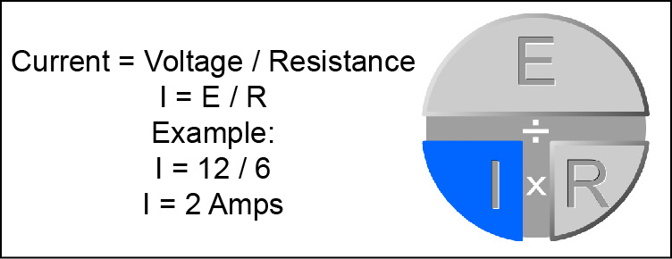
Figuring current
If you know what the voltage and resistance is you can easily determine exactly how much current there is in a circuit.
To figure current flow you need to know the voltage applied and the resistance of the circuit. Using ohms law, take the voltage and divide it by the resistance in the circuit. An example would be if you had 12 volts applied to the circuit with 6 ohms of resistance you would divide 12 volts by 6 ohms to get 2 amps of current flow.
To Be Continued . . .
Hopefully, you found this article helpful in understanding some of the basic components of electrical circuits and the relationship that exists between voltage, current, and resistance.
In the next issue, we will be covering open circuit measurements, and voltage drop tips to help you with performing the diagnostic process during electrical troubleshooting.