
Generally speaking, today’s A/C systems are pretty reliable. There are many factors that can affect an A/C system’s performance. And, you should not forget your customer’s perception of their A/C system’s cooling capacity. If there are any customer complaints like “no cool air” or “insufficient cool air”, the signs and the symptoms described by your customer and what you observe are the clues you’ll need to trace the source of the problem and understand your customer’s expectations. Observe and validate the symptom from the customer’s information, isolate, repair, and then retest.
The most common diagnostic techniques are:
- Examination
- Observation
- Look in ASIST® for applicable TSBs
- Performance Test
- Touch and feel diagnosis
- Self-diagnosis
- Manifold gauges or A/C Service Center
- CONSULT
- Leak detection
is possible there might be some visible signs of trouble that you may be able to spot easily. Look to see if you can observe frost or ice on a Thermostatic Expansion Valve or liquid tank. This can indicate an internal restriction. Look to see if there is any debris blocking air flow through the condenser. Something on the front of the condenser would restrict air flow which could be the cause of poor cooling.
Observation sometimes is done best with the aid of testing devices. Keep in mind that no instrument can tell you what’s wrong with a system - it just gives you the information you’ll need to diagnose the possible cause of an issue. Check for proper system function and operational performance to help narrow down and isolate any symptoms. Start with your customer’s information and check for any obvious problems and possible engine overheating:
- Is belt tension within specification?
- Is there sufficient refrigerant in the system?
- Does the A/C switch indicator turn on and operate the compressor?
- Is the compressor clutch engaged? Is it engaged with the switch in the off position?
- Is there sufficient air flow coming from the vents?
- Check and verify the air mix door mechanism for smooth operation.
- Is the In-Cabin Micro Filter blocked or fan full of debris?
Perform a basic system inspection of the A/C control system. The purpose of these operational checks is to confirm that each of the individual systems operates normally and maintains correct settings when the engine is running at normal operating temperature.
- Make sure you check the operation of all discharge modes including face, bi-level, foot, and foot/defrost.
- Press the off button and turn the ignition OFF, then ON and press the AUTO button to confirm the set temperatures are maintained.
- Check to see if the temperatures can be increased and decreased.
- Operate the fan control.
- Check that the fan speed changes.
- Check the operation for all blower speeds.
- Listen for changes in the blower speed as the set temperature changes.
- Don’t forget to check the power supply and ground circuit of the A/C auto amp.
- Confirm the compressor clutch engages.
Remember, the compressor clutch will not engage with the fan in the OFF position.
NOTE: This step does not check that all auto functions are working. It only verifies that the system goes into Auto mode.
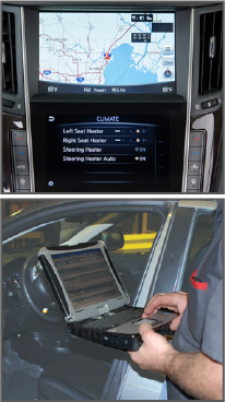
Use the onboard self-diagnosis or use your CONSULT to check for any A/C system DTCs. If any DTCs are found, perform a trouble diagnosis for the detected DTC.
Checking for Leaks
The engine compartment environment tends to be on the harsh side due to vibration and heat. Over time, these conditions can take their toll. So it’s a good idea to carefully check system pressures and inspect all refrigerant parts, fittings, hoses, connections and components for signs of A/C lubricant leakage, refrigerant line damage or component corrosion.
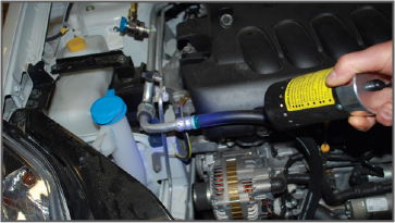
Make sure everything is clean and dry. A refrigerant leak will show up as a damp area at the point of leakage. Very likely, dust will have collected on this area as well. Use an electronic leak detector probe in conjunction with a fluorescent dye leak detector to help pinpoint refrigerant leaks. Calibrate the leak tester if required and perform the leak test from the high-pressure side (front A/C compressor discharge to the evaporator inlet or rear piping connection), then the low-pressure side (front A/C evaporator drain hose to shaft seal and rear A/C evaporator drain hose to the piping connectors). Do not stop when one leak is found but continue checking for additional leaks at all system components and connections. Be sure to perform leak testing with the engine off and away from fans or sources of high airflow which may diminish test results. (REMEMBER- if working on the hybrid or an electric vehicle system there is no dye in the system and dye should not be introduced into the system due to the electric compressor).
NOTE: A fluorescent dye leak detector is not a replacement for an electronic refrigerant leak detector. A positive dye mark may be residual from prior testing, so it is best to clean the dye from the area and retest.
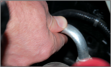
“Touch and Feel” Diagnostic Process
Don’t forget a tool in your toolbox that can help you identify the root cause of a customer’s A/C concerns: the “touch and feel” diagnostic process. The term “touch and feel” might sound a little strange, but it’s still an industry accepted method for helping to isolate some A/C issues. During A/C system operation, there will be predictable temperature ranges on the inlet and outlet side of the A/C components. If there’s a pinched tube, the tube will be icing or very cold after the point of restriction (in the direction of refrigerant flow).
NOTE: Collision damage can sometimes crimp tubes without breaking them, causing a restriction rather than a leak.
Whenever you’re working on a customer’s vehicle and you find a section of heater coolant or A/C refrigerant hard tubing that is damaged, use the J-41425-NIS Tubing Repair Kit. This aluminum tubing repair kit can save you a lot of time and effort because it provides you with the ability to splice in a new piece rather than replace the whole line. If you see signs of leakage at a connection point, check it using the procedures in the ESM. Replace any damaged seals and O-rings, being careful not to damage the new ones. After repairing or replacing a line or a connection point, recharge with the proper amount of refrigerant, and do a system leak-down test to verify the integrity of the A/C line and all the connection points seal properly. You’ll need to apply vacuum to the system to see if it holds the vacuum for a specified time frame.
When diagnosing and servicing the A/C system on a R-134a vehicle, we highly recommend you use the Robinair Recovery, Recycling, and Recharging Unit Model 4971. This A/C service equipment is designed to be compatible with existing service equipment and standard service procedures. It helps make these checks easy to perform and ensures accuracy. It provides you with timesaving features like automatic air purge, single pass recycling, and automatic oil drain. In addition to the essential Robinair 4971, the original ACR-5 is still acceptable and used by most dealerships. Keep in mind the system will not charge if a vacuum leak is detected. Newer refrigerant line connections use different O-ring configurations. Never confuse the new “one-touch” connection with the previous connection O-rings because they are not interchangeable. Be sure to apply compressor oil when installing them.
It’s Not Magic, It’s Still the Basics
Luckily, Nissan and Infiniti vehicles have the same basic A/C refrigerant loop components that are connected to each other with tubing and hoses forming a closed loop for the “refrigeration cycle.” Air conditioners work by compressing a gas into liquid and then evaporating it back into gas again. The operation of the A/C system is quite simple; it removes heat and moisture from the air inside the vehicle and transfers it to the outside air. So how does that apply to making a vehicle’s vents blow cool air? The refrigerant flows from the compressor, through the condenser with liquid tank, through the evaporator, and then back to the compressor. The refrigerant evaporation in the evaporator is controlled by an externally equalized expansion valve located inside the evaporator case.
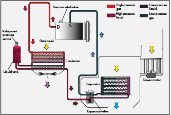
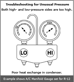
The compressor’s job is keeping refrigerant flowing and to compress lowpressure gas into high-pressure gas. The refrigerant system is also protected by a pressure relief valve located in the rear head of the compressor. If the pressure of refrigerant in the system increases to an abnormal level [more than 2,990 kPa (30.5 kg/cm2, 433.6 psi)], the release port on the pressure relief valve automatically opens and releases refrigerant into the atmosphere. You might want to check with the compressor manufacturer but the rule of thumb says once this valve opens, repair the valve. If it weakens with use it could open at lower pressures. The condenser turns the higher pressure refrigerant from a gas to a liquid by removing the heat the refrigerant collected from the vehicle's interior via the evaporator. Leaves, plastic bags, dirt, or other debris can stick to the fins of the condenser, or between the condenser and radiator and block airflow. Obstructed airflow through the condenser causes poor cooling performance. If there’s an airflow issue, use the “touch and feel” diagnostic method. If the condenser inlet and outlet tubes are both the same temperature (the inlet should be hotter than the outlet), it’s likely that no heat is being released from the refrigerant as it passes though the condenser. When you check pressures, both high- and lowside pressures will be higher than normal.
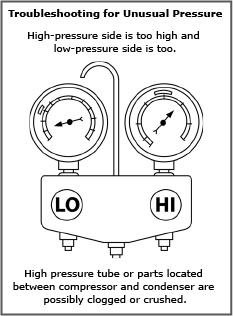
NOTE: Be sure to observe the location of the service ports. For years, the high-side port was located between the compressor and condenser. However, now its located between the condenser and evaporator on many models. This greatly changes your diagnosis results when checking pressures. For example, if there was a restriction in the condenser or liquid tank (receiver-drier), high-side pressure coming from the relocated service port would be lower than normal, whereas it would be higher than normal with the port before the condenser and tank.
Under high ambient temperature conditions, and especially at low speeds, an inoperative condenser fan can cause the same symptoms as obstructed airflow, so make sure the condenser fan is working.
If the condenser has internal restrictions, the air conditioner will be less efficient. Touch and feel diagnosis will show the low side is not as cold as it should be, and the high side after the condenser may feel cool. The high-side pressures will likely read HIGHER than normal (depending on port location), and low-side pressures will read LOWER than normal.
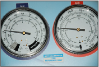
NOTE: Be certain that the manifold gauge set face indicates HFC-134a or R-134a. Be sure the gauge set has 1/2” - 16 ACME threaded connections for service hoses. Confirm the set has been used only with refrigerant HFC-134a (R-134a) and specified lubricants.
The primary purpose of the evaporator is to absorb heat as it transforms high-pressure liquid refrigerant into gas by evaporation. A secondary function is dehumidification. As warmer air is brought in from the cabin and travels through the fins of the cooler evaporator coil, the moisture contained in the air condenses on its surface and drains out through the drain hose. The warm air passing through the evaporator fins causes the refrigerant to boil because refrigerants have very low boiling points. As the refrigerant absorbs large amounts of heat from the vehicle’s interior in the evaporator, it begins to boil. The refrigerant then releases this heat as it circulates through the condenser. The expansion valve located inside the evaporator case senses both temperature and pressure. The expansion valve’s job is keeping pressure in the evaporator low, allowing the refrigerant to boil, thus absorbing heat. Electronic sensors keep the evaporator from freezing by either cycling the A/C clutch or adjusting the displacement of the compressor. A frozen evaporator will not absorb as much heat. It also greatly reduces the pressure on the liquid refrigerant affecting its flow back to the compressor. When an expansion valve is not functioning properly (stuck closed, partially restricted or wide open), it will cause the interior vents' discharge air to become warmer. If too little refrigerant enters the evaporator, the system will not cool effectively because a smaller amount of refrigerant absorbs less heat or boils away. If too much refrigerant enters the evaporator, the system will not cool effectively either.
NOTE: It is vitally important that only vaporized refrigerant leaves the evaporator. If liquid refrigerant leaves the evaporator it can damage the compressor.
Make sure to check the power supply, signal and circuit continuity between the ECV (Electric Control Valve) and the unified meter and A/C amp. Also make sure the compressor is emitting the appropriate amount of refrigerant when necessary.
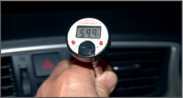
Check Air Temperature Coming Out Of the A/C Vents
After you’ve checked the refrigerant loop components, continue with your A/C system operational checks and performance checks inside the vehicle’s cabin. With ambient (outside) temperature in the mid 70°F range and humidity at 50%, the A/C temperature coming out of the vents might typically be around the mid-to-upper (47 - 52°F) range. This is in RECIRC mode and depends, of course, on the system temperature setting. The ambient temperature and humidity will definitely affect A/C performance.
A customer might state that the temperatures they feel are different than the airflow temperature controlled by the temperature setting. If a customer complains that the left and right outlet temps are different, this is usually a low charge condition. It may also cause some freeze ups (or a no flow to low flow airflow condition). That could be the case because, on ATC equipped vehicles, the vent temperature may not be the same as the temperature setting. Because the system is trying to get the cabin temperature to the temperature setting, the vent air may have a much colder or hotter temperature, depending on the temperature setting. For example, if the cabin temperature is 90°F and the temperature setting is at 70°F, vent air temperature will at first be colder than the temperature setting. As the cabin temperature gets closer to the temperature setting, the vent air temperature will get closer to the temperature setting. The auto amplifier control temperature can be adjusted to compensate for the customer’s preference.
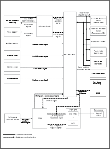
The A/C auto amp controls front automatic air conditioning system by inputting and calculating signals from each sensor and each switch.
Have Trim Settings Been Cancelled Due to the Battery Being Disconnected?
If the battery cable was ever disconnected from the negative terminal or the battery voltage reading is 10V or less, any of the customer’s preferred settings such as Temperature Setting Trimmer, Foot Position Setting Trimmer, and Inlet Port Memory Functions may have been cancelled, causing the setting to default to the factory setting. Changes in these settings will affect the air temperature coming from an outlet. The Electronic Service Manual (ESM) will guide you through the checks to perform if the system isn’t cooling well enough.
Automatic Temperature Control (ATC)
The Automatic Climate Control (ATC) concept has been around since the 1950s. The first truly automatic system was introduced on the 1964 Cadillac. Cadillac owners could theoretically drive from coast-to-coast without having to adjust the controls, because the passenger compartment was automatically maintained once the system temperature was set. Flash forward to 2013. Modern ATC systems still maintain the selected cabin temperature at a preset comfort level, year-round. But, thanks to decades of technical development – particularly in the area of electronic controls – today’s ATC systems cool, heat, dehumidify, defrost, and defog, while keeping a constant temperature and filtering the air to deliver a level of performance no one could have imagined in 1964. In Nissan and Infiniti systems, the driver can choose to control the system manually, or allow the system to run automatically.
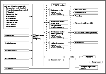
This is done with built-in microcomputers to process information sent from various sensors needed for the air conditioner’s operation. The fan speed and the air mix doors are automatically controlled so that the in-vehicle temperature is maintained at the predetermined value of the temperature setting. A/C performance is influenced by the ambient temperature, in-vehicle temperature, the amount of sun load, humidity, as well as the ON/OFF operation of the compressor. While air is being drawn from outside the vehicle, or during recirculation, it is dehumidified through the A/C system and then partially cleaned with the replaceable in-cabin micro filters to help improve the air quality in the vehicle by reducing the amount of pollen and other particulate pollution.
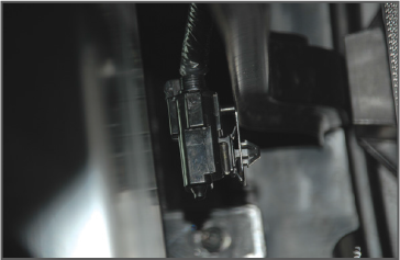
If the air conditioner will not blow cold even though the refrigerant loop is functioning properly, the ambient sensor is a possible cause. If the ambient sensor doesn’t work properly, the ATC system microprocessor won’t be able to determine the correct outside temperature. If the circuit is open (as if the sensor was disconnected), there will be infinite resistance to the voltage signal and the ATC system microprocessor will interpret this as a very low temperature. As a result, the microprocessor won’t send a signal to turn the compressor ON. The ambient sensor is a tough little “workhorse”. However, it’s located at the front of the vehicle so it’s exposed to more severe conditions than some of the other sensors.
Self-diagnosis system
Self-diagnosis functions are built into many Nissan and Infiniti electronic A/C control systems. These self-diagnosis functions can help you quickly locate the cause of some A/C performance issues. Check for malfunctioning sensors and door motors, blower motor, etc. Refer to the applicable ESM for details.
Manual Heater and Air Conditioning Controls
Understanding heater and air conditioning controls and their intended functions and performance characteristics can help you inform your customers so that they fully understand and utilize their vehicles’ Heating, Ventination, and Air Conditioning (HVAC) system capabilities.
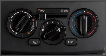
Rotary Controls
With rotary ATC controls, the driver sets the temperature level using a rotary dial. The system continuously measures exterior temperature, interior temperature, and sunload intensity. When the fan control switch is in the auto position, the ATC system varies fan speed to automatically maintain the preset temperature, but it does not automatically open and close airflow distribution vents. Blower fan speed is also manually controlled with the dial for varying blower speed.
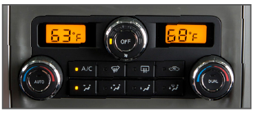
Digital Controls
With digital ATC controls, the driver sets the temperature level using a digital readout. The system also measures the temperature of the air entering the system. It varies both fan speed and airflow distribution to automatically maintain the preset temperature.
Dual-Zone Controls
Dual-zone controls provide separate control functions for the left and right sides of the cabin which allow the driver and front-seat passenger to individually establish their own temperature settings, depending on personal preference or sunload on each side of the vehicle.
Advanced Climate Control System (ACCS)
The Advanced Climate Control System (ACCS) adapts automatic climate control by enhancing cabin air quality filtration as well as temperature. It has three key features: a Plasmacluster™ Air Purifier, a grape seed polyphenol filter and an auto-recirculation function. The plasma cluster deodorization filter is saturated with natural grape seed polyphenol, which makes it highly efficient in eliminating allergens that can cause pollen allergies.
Conventional filters are designed to block mainly dust and pollen particles with a minimum size of 10 microns. However, they are not very efficient in blocking smaller particulates (up to about 1 micron in size) or other allergens, especially allergy-causing pollen that can be as small as 0.3 to 0.5 microns.
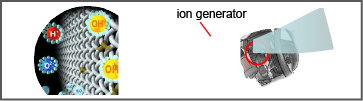
The three-dimensional molecular structure of natural grape seed polyphenol traps the smaller allergen molecules and deactivates them. The antibacterial properties of natural grape seed polyphenol filters are about 1.5 times better than conventional filters. The Plasmacluster™ Air Purifier has two modes that operate all the time and switch back and forth automatically: Clean mode and Ion mode. Clean Mode emits a low concentration of negative and positive ions that attract airborne particles (mold, fungi, spores, etc.). Once ionized, the particles attach themselves to water molecules in the air of the cabin and become residue. That residue is then filtered as it gets pulled through the incabin microfilter or grape seed polyphenol filter.
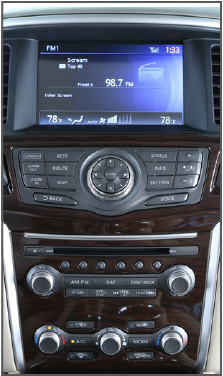
When Clean Mode is operating, the ion symbol on the vehicle’s Information Display screen illuminates blue.

Ion Mode creates a high concentration of negative ions, imparting a freshness and crispness to the cabin air. Cabin air smells clean, similar to what you experience after a thunderstorm or standing near a waterfall.
When Ion mode is operating, the ion symbol on the vehicle’s Information Display screen illuminates green.
If an odor is noticed, confirm the filter has been changed and it is clean (Grape Phenol is recommended). Confirm that the evaporator drains correctly. If the odor is persistent, and the vehicle is utilized in a high humidity area, suggest to the customer that just prior to parking, they shut of the AC to let the blower dry off the evaporator. This will help to reduce the mold environment and help keep the stinky odor from taking place.
ACCS Recirculation Mode is Automatically Activated
The ACCS system remains in the fresh air mode in normal driving conditions, such as on highways or suburban streets with moderate traffic. In driving conditions where there is a high level of exhaust gases— such as stop-andgo traffic or when driving through a tunnel— an external sensor signals the system to switch to recirculation mode, helping prevent the exhaust gases from entering the passenger cabin.
The auto-circulation system sensor senses only exhaust gases or other pollutants, not unpleasant odors. If you drive over a dead skunk in the road or past a landfill or smelly barnyard, you will smell the odor for a while. However, the Plasmacluster air purifier eventually removes the smell and cleans the cabin air. When the auto-recirculation function is ON — thanks to the grape seed polyphenol filter — about 90% of allergens and germs in the cabin air are removed within five minutes, and 99.5% are removed within 15 minutes.
In Summary
If you perform any A/C service on a customer’s vehicle, remember to get printouts on all repairs/diagnosis. It is required for warranty!
As climate control systems advance allowing drivers and passengers to choose and maintain their own comfort level settings, Nissan and Infiniti vehicles will continue to provide state-of-the-art responsive zonal and automatic controls for enhanced comfort.