![]()
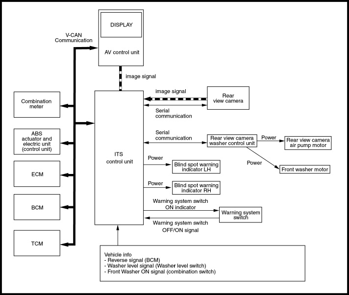
The 2013 Altima and Murano can be equipped with the Intelligent Technology Suite which includes Blind Spot Warning, Lane Departure Warning, and Moving Object Detection. All of these systems use the RearView camera located near the rear bumper when the system is turned ON by operating the warning systems switch of the Advanced Driver Assist system. The ITS control unit controls each system based on the signals received from the RearView camera and CAN communication signals received from each control unit. The system does not operate properly unless the RearView camera aiming adjustment is performed.
The RearView camera detects the lane markers in the lane of travel and transmits the lane condition signal to the ITS Control unit.
Work Procedure
PERFORM SELF-DIAGNOSIS
Perform self-diagnosis of the ITS control unit.
Is any DTC detected?
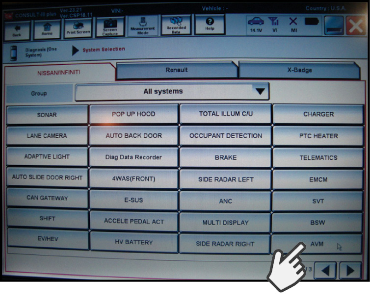
NOTE: Select the "AVM" to diagnose the ITS control unit by CONSULT.
When to Perform RearView Monitor Calibration:
- After removing and installing the rear camera unit
- When DTC U1305 Camera Config is current in "Self Diagnosis Results" of the AVM
- When DTC U1308 ITS Calib (ITS control unit calibration is incomplete) is detected
- When the ITS or AV Control Units are replaced
PREPARATION OF VEHICLE
A. Perform "Inspection Procedure":
- Clean the RearView camera lens.
- Inspect RearView camera unit installation condition (installation position, properly fitted).
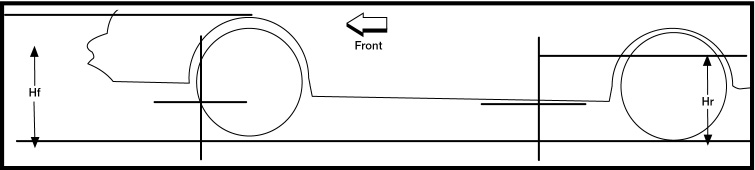
- Measure the vehicle height. Refer to ESM FSU-section Wheel Height Arch (vehicle un-laden).
B. Before performing Wheel Height Arch Measurement:
- Adjust the tire pressure to the specified pressure value.
- Remove any stored objects, loads or packages from the vehicle.
- Check the vehicle's fluid levels to ensure that the coolant and fuel levels are full, and that the engine oil is filled up to correct level.
- Place the vehicle where the RearView camera will be exposed at an ambient temperature between 32°F (0°C) and 86°F (30°C).
- Move the shift selector into the P (Park) position and release the parking brake.
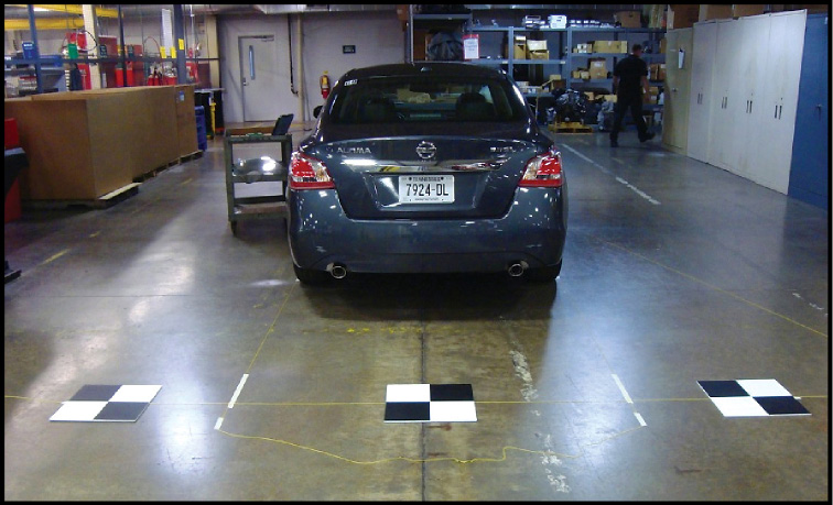
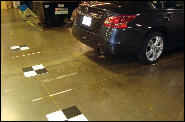
PLACEMENT OF J-51179 Rear View Camera Calibration Targets
To perform the target setting procedure, stage the vehicle on level ground. Place the vehicle where it is clear of any objects or obstruction around it with a clear view behind it for 9.84 ft (3 m), and 13.12 ft (4 m) to either side.
NOTE: If possible it is desirable that the vehicle be positioned on a clean, single-colored floor.
When using the J-51179 Rear View Camera Calibration Targets, it's a good idea that they be placed in a well-lighted location. (Poor lighting may make it hard to see and adjust).
- The targets may not be detected when they are reflecting light from the sun or too much bright light.
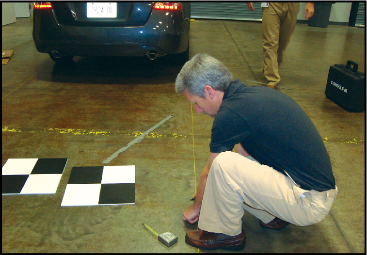
- Make sure that the black/white pattern of the center target is rotated as compared with the left and right targets next to it. The targets may not be detected correctly if they have the same pattern of black or white as the target that's next to them.
Target Setting
'The following tools are needed: A plumb bob, a chalk line or string, a marker, tape, a tape measure with millimeters, and a 12" straight ruler.'
1. To begin, hang a plumb bob, drop it down from the top of the fender opening, through the center of each wheel, to the floor. Make a mark indicating the center of each wheel on a piece of tape on the floor.
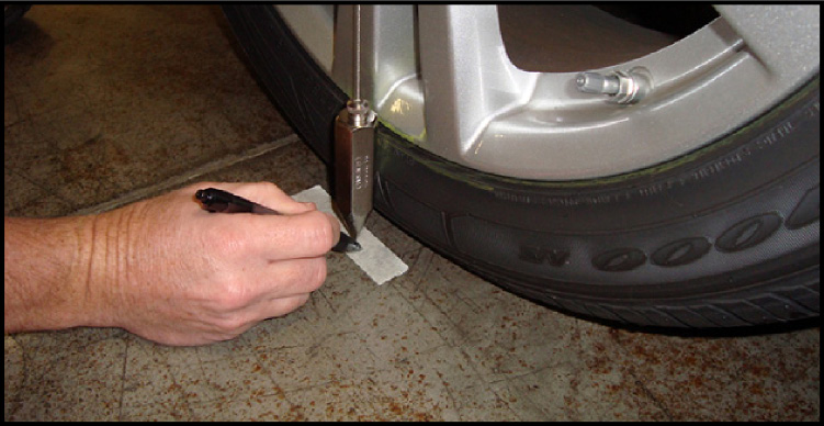
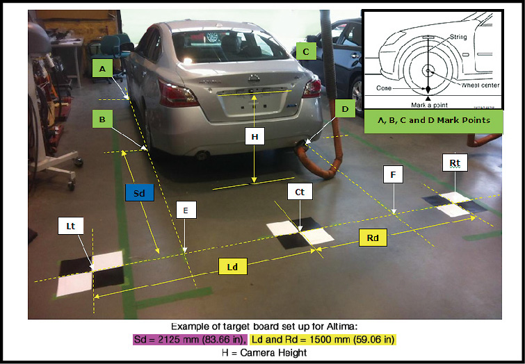
Mark points "A", "B", "C" and "D" at the center of the lateral surface of each wheel as shown.
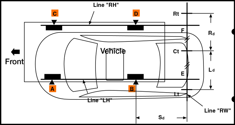
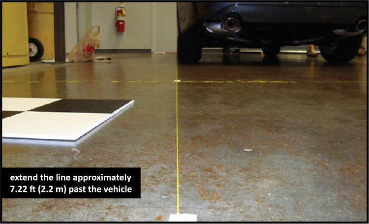
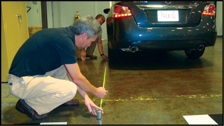
2. Next, snap a chalk line, or stretch string for the "LH" passing through points "A" and "B" on the left side of vehicle.
NOTE: Whether you are performing RearView Monitor Calibration on an Altima or a Murano, you will need to extend the line approximately 7.22 ft (2.2 m) or more past the rear of the vehicle beyond the rear axle.
3. Mark point "E" on the "LH" line, at 83.66 in. (2125 mm) from point "B", to establish the distance for the target setting line at the rear of an Altima vehicle. If working on a Murano vehicle, mark point “E” on the “LH” line, at 69.88 in. (1775 mm) from point “B”, to establish the distance for the target setting line.
4. Now, snap a chalk line, or stretch string line for the "RH" passing through points "C" and "D" on the right side of vehicle (the same as you did on the left side of the vehicle). Remember, you'll need to extend the line 7.22 ft. (2.2 m) past the vehicle on this side as well.
5. Mark point "F" on the "RH" line, at 83.66 in (2125 mm) from point "D", to establish the distance for the target setting line on the other side of an Altima vehicle. Mark point “F” on the “RH” line, at 69.88 in.(1775 mm) from point “D”, to establish the distance for the target setting line on a Murano vehicle.
6. Now, snap a chalk line, or stretch string line for the "RW" target setting line that passes through the points "E" and "F" at the rear of the vehicle.
NOTE: Mark the chalk line or stretch a string to approximately 5.91 ft (1.8 m) or more beyond both left and right sides from vehicle center.
7. Measure and mark point "Ct" at the center point between "E" and "F" on the "RW" target setting line.
![]()
Make sure that "E" to "Ct" is equal to "F" to "Ct" in order to correctly position the target points for the boards.
8. Mark point "Lt" and "Rt" on the "RW" line, by measuring 59.06 in (1500 mm) from the center point "CT" for an Altima. On a Murano, mark point “Lt” and “Rt” on the “RW” line, by measuring 57.87 in (1470 mm) from the center point “Ct”.
9. Now position and arrange the 3 targets centering them on the target points you made on the "RW" target setting line.
NOTE: Make sure that the black/white pattern of the center target is rotated as compared with the left and right target boards.
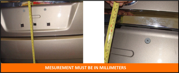
Check RearView Camera Height
Before starting RearView Monitor calibration with CONSULT, measure the position of the RearView Camera from the ground. Write down the RearView Camera height "H". This measurement must be in millimeters as this is how it is input into CONSULT.
REARVIEW CAMERA CALIBRATION
Connect the CONSULT VI, and then switch the IGN to ON.
IMPORTANT NOTE:
Launch C-III plus from the PC desktop, (Do Not start CONSULT from ASIST, or the RearView Camera Calibration will not function).
Operate CONSULT outside the vehicle, and close all door s to retain appropriate vehicle altitude while performing this procedure.
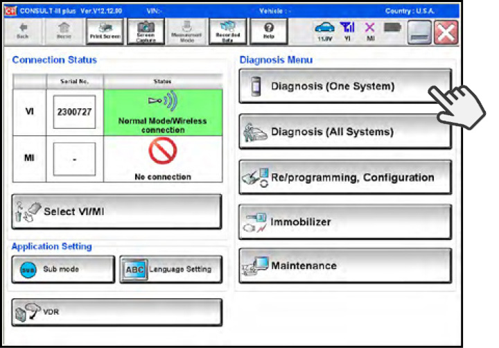
A. Select "Diagnosis One System" from the CONSULT Home page.
B. On the System Selection page, use the arrows at the lower right corner of the screen to page forward until you find the AVM system.
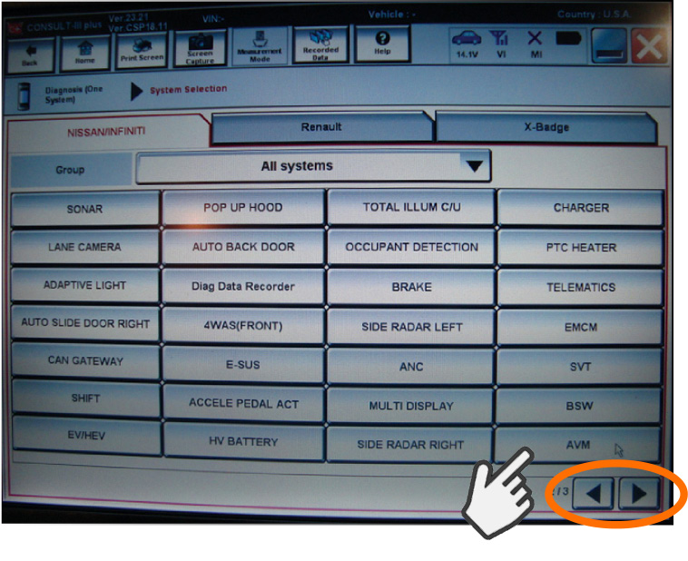
C. Select AVM. After the System Call, CONSULT will display the Self Diagnosis Results Screen.
NOTE: If any DTCs are present other than U1305, and/or DTC U1308, diagnose and repair them before continuing.
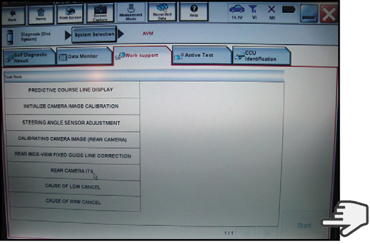
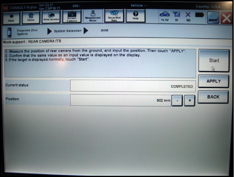
D. Next, Select "Work Support" in "AVM" with CONSULT.
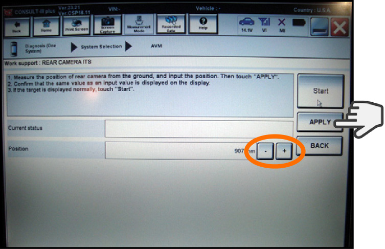
E. 'Select REAR CAMERA ITS, Start, and then OK. The Rear Camera ITS input screen will display.
F. Use the + (plus) and - (minus) buttons to adjust the Position display to match the Rear height measurement you wrote down. After you've adjusted the Position value, select the "APPLY" button.
G. Enter the vehicle and confirm that the value measurement you entered in CONSULT is applied by verifying that the same value is displayed on the vehicle's RearView Monitor. The numbers listed on the upper right should indicate the Roll Height is adjusted to the same Position Value you input into CONSULT.
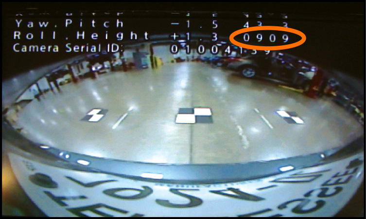
H. If the Roll Height numbers value DO NOT match the Position Value you input, restart the process with CONSULT.
Confirm the following items:
- The targets have been placed accurately.
- The vehicle has not been moved.
- The vehicle should still be under the specified vehicle condition performed earlier.
IMPORTANT NOTE:
You must wait a minimum of 10 minutes to allow the vehicle and camera to stabilize. The calibration will not initialize if you skip this step. Operate CONSULT outside the vehicle with all doors closed (this will retain proper vehicle level).
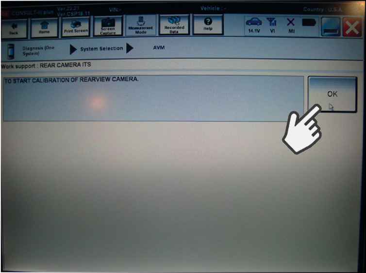
I. After 10 minutes, select "OK" on CONSULT to initialize calibration.
J. Calibration only takes a few seconds. Confirm that CONSULT displays:
- "Completed": Select "Completion".
K. Confirm that "Completed" is displayed and then sele ct "Back" to close the calibration procedure.
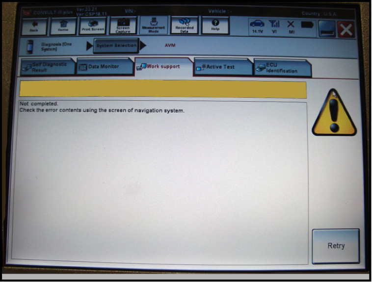
If it displays "Not completed," perform the following services below:
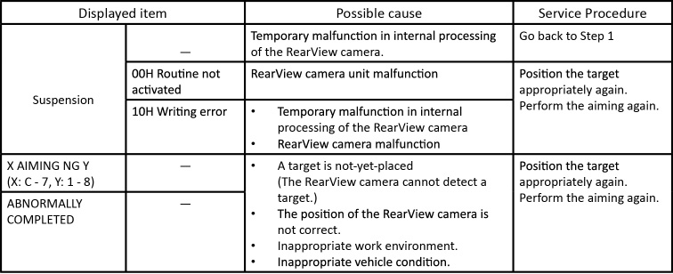
NOTE: Replace camera unit if "00H Routine not activated" or "10H Writing error" are repeatedly indicated during the above two services.
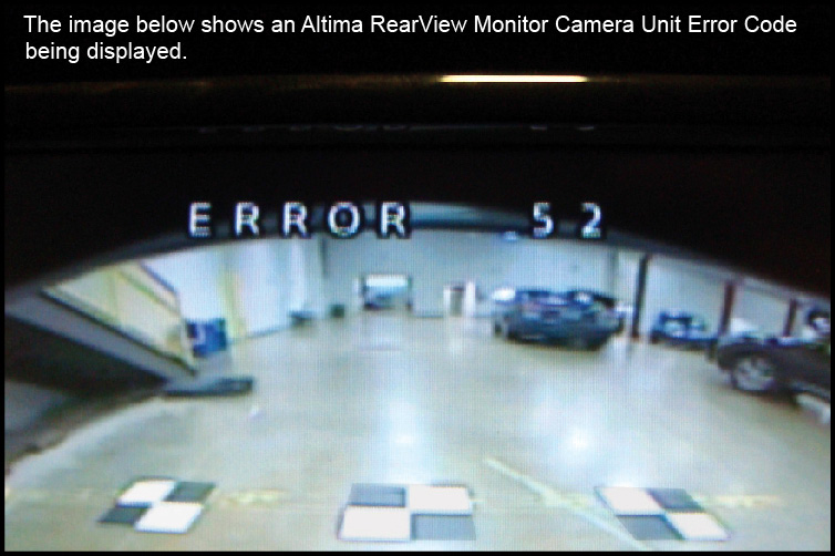
ERROR CODES
If CONSULT displays "Not completed":
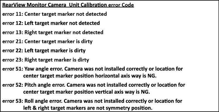
Enter the vehicle and look for an ERROR CODE displayed on the vehicle's Rearview Monitor. If a RearView Monitor Camera Unit Error Code is displayed it will help you to determine what may have caused the calibration not to complete. The ERROR Codes only display for about 5 seconds. But touching the "Retry" button on CONSULT will retry the system aiming again, and if still not complete the ERROR CODE will again display on the RearView monitor.
Final Steps:
PERFORM SELF-DIAGNOSIS
Perform self-diagnosis of ITS control unit with CONSULT.
Is any DTC detected?
YES >> Perform diagnosis on the detected DTC and repair or replace the applicable item.
ACTION TEST
The final step is to perform an action test to verify the system operation. Check system settings and perform driving test.
>> Work End.