Replacing a Li-ion Battery Cell or Module
The Lithium-ion Battery Controller (LBC) in the LEAF™ performs cell capacity adjustment when the system starts. At this time, the capacity of each cell is estimated based on no-load voltage. This process ensures the capacity of each cell is adjusted so that they are all at the target level. The voltage of each cell is detected by the LBC which sends requests to the Vehicle Control Module (VCM). The VCM receives the Li-ion battery available charge signal from the Li-ion battery controller, judges the battery load based on these signals and controls the power generation by converting the target generation voltage. It optimizes the target charge power based on the Li-ion battery sending the maximum charge power signal to the on-board charger. This helps to prevent an error such as overvoltage, over discharge, or excessive temperature rise in the battery.
If necessary, the bypass switches are turned ON by the LBC to discharge the cells that have excess capacity. This allows the capacity of all cells to be fully utilized.
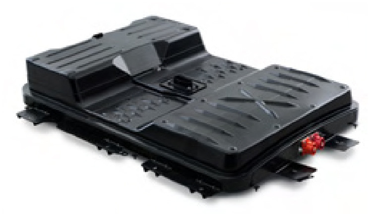
The individual cells and modules in the high voltage Li-ion battery in the LEAF™ vehicle require periodic inspection to verify the battery’s capacity. If a cell voltage reading (e.g., abnormal voltage DTC or a module over discharge) is detected in a Li-ion battery cell, the module which includes the malfunctioning cell must be replaced. If an abnormal cell is not identified, perform a DTC confirmation procedure. Refer to your ESM.
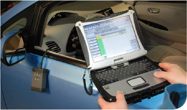
It’s also important to check the cell voltage with CONSULT by performing a cell voltage loss inspection.
Note: The cell voltage loss inspection is performed to identify cells where the cell voltage is decreasing from the standard value, or, when the minimum voltage is 3.712mV or less. If the cell voltage is on the decrease (although not judged as malfunction in DTC) this may be an indicator that a decrease is leading to a malfunction.
Average cell voltage = “TOTAL BATTERY VOLTAGE” + 96
Cell voltage loss judgment value = Average cell voltage - (“MAXIMUM CELL VOLTAGE” - Average cell voltage) x 1.5
If cell voltage loss inspection has determined that a cell voltage is on the decrease (although not judged as a malfunction in the DTC), the module including this cell may need to be replaced.
FREEZE FRAME DATA (FFD)
Save the FFD of the vehicle status when a DTC is detected and is displayed on CONSULT.
Important Note: You’ll refer to the CELL VOLTAGE 01 - 96, to calculate the target voltage. This is because you must adjust the new module voltage using a Module Charger/ Discharger to match the remaining modules before installing in the battery. This procedure will be discussed later in this article.
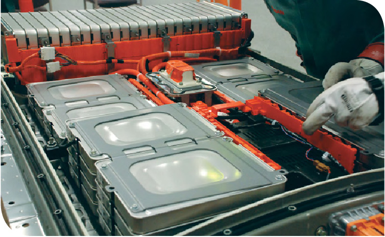
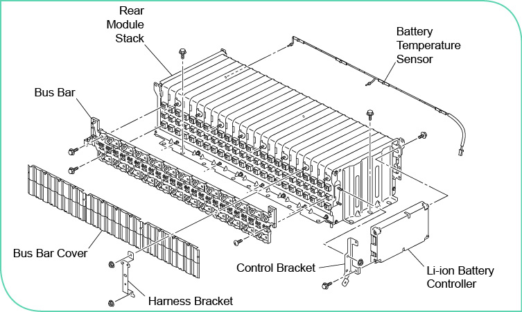
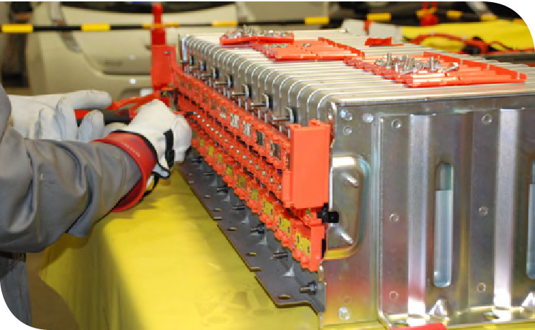
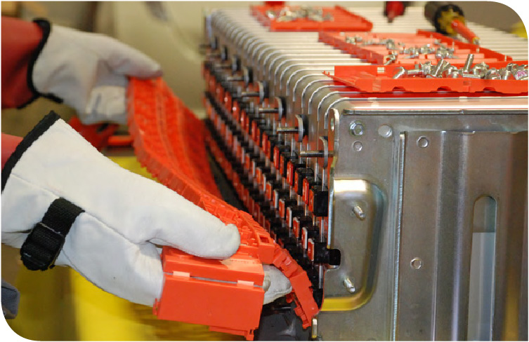
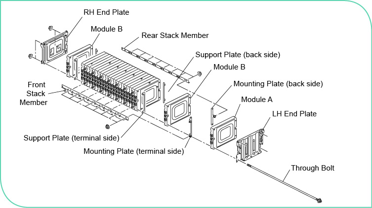
The following information is intended to provide you with some helpful tips for performing the battery module pack disassembly and assembly service (exampled on a rear module stack).
![]()
DANGER
- Because hybrid vehicles and electric vehicles contain a high voltage battery, there is the risk of electric shock, electric leakage, or similar accidents if the high voltage components and vehicle are handled incorrectly. Be sure to follow the correct work procedures when performing inspection and maintenance.

- Always remove the service plug in order to disconnect the high voltage circuits before performing inspection or maintenance of high voltage system harnesses and components.
- To prevent the removed service plug from being connected by mistake during the procedure, always carry it in your pocket or put it in the tool box.
- Be sure to wear mandatory P ersonal Protective Equipment (PPE) consisting of gloves, shoes, face shield and a CEB2GY Coverall before beginning work on the high voltage system.
- It is imperative to clearly identify the persons resp onsible for high voltage work and ensure that other persons do not touch the vehicle during high voltage system maintenance. When not working, cover high voltage parts with an insulating cover sheet or similar item to prevent other persons from contacting them.

- Always refer to the Disassembly/Assembly procedures in the ESM. Disassembly and assembly requires the high voltage insulated tools included in the Electric Vehicle Lithium-ion Battery Service Kit (J-50249).
- Be sure to follow the procedures in the ESM for disconnecting the high voltage system.
![]()
PRECAUTIONS FOR STORAGE OF THE LI-ION BATTERY
- Apply insulating tape to the service plug and high voltage harness connector, and protect the terminals so that nothing can contact them.
- Store in a well-ventilated location that is not exposed to direct sunlight. (Storing outdoors or unprotected is prohibited.)
- Never set the battery directly on the floor.
- Always lay an anti-static rubber sheet underneath the battery.
- Never invert the battery.
- Never stack batteries.
- Cover with an anti-static cover sheet.
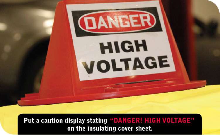
- Put a caution display stating “DANGER! HIGH VOLTAGE” on the insulated cover sheet.
- Put an identification display showing the name of person in charge on the insulated cover sheet.
- Never allow water to contact the battery.
- Prevent other objects from falling onto the battery.
Disassembly Of The Li - Ion Battery
1. Clean any contamination and dust from the battery pack.
2. Remove the service plug retainer plate.
Note: This will require a Torx T30 Tamper Proof Security bit.
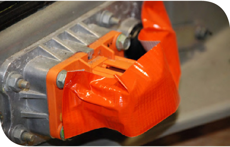
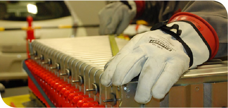
Note: During disassembly immediately cover all the harness connectors with insulating tape to prevent moisture, dirt, or debris from entering a connector. “Heads Up!” - The insulating tape has a tendency to stick to the insulating rubber gloves. Prepare strips of tape folded over at the ends beforehand, to make handling the tape easier.
3. Remove the mounting bolts and mounting nuts, and battery pack, and then remove the upper case from the battery pack.
Note: Removing the upper case of the battery pack, and some of the other procedures, will require two people, both wearing insulated Personal Protective Equipment (PPE).
4. Disengage the pawls and remove the battery junction box cover.
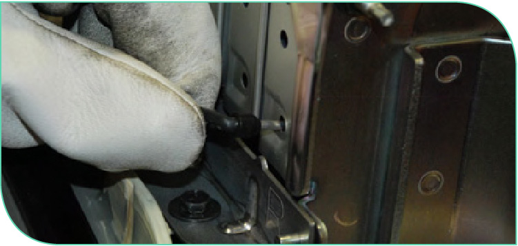
5. Remove the terminal mounting nuts of the high voltage harness connector.
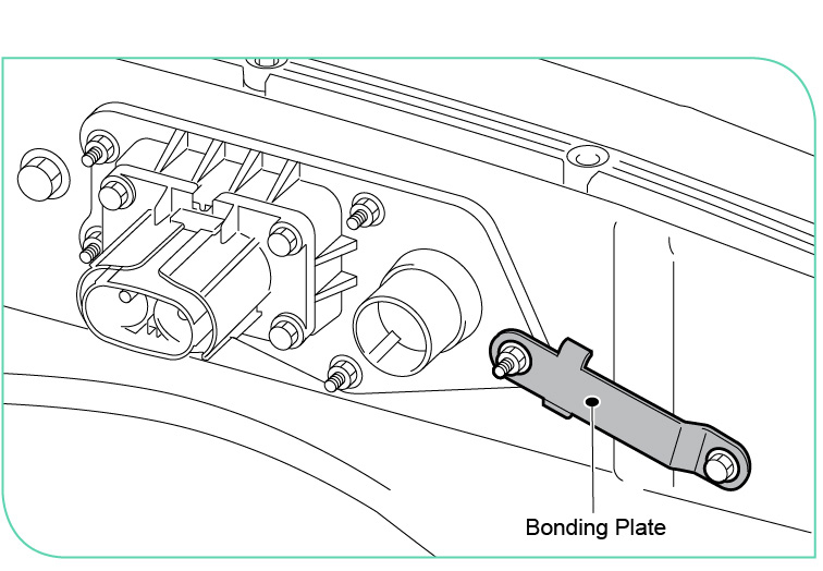
6. Remove the mounting nut and mounting bolt, and then remove the bonding plate.
Helpful tip: Use the module stack diagram in the ESM and your CONSULT inspection results to identify the failed module from the DTC stored in the VCM. Then, mark the module that is to be replaced with a piece of tape or permanent marking pen.
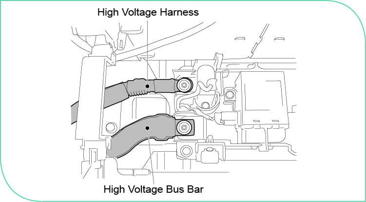
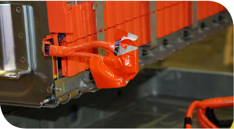
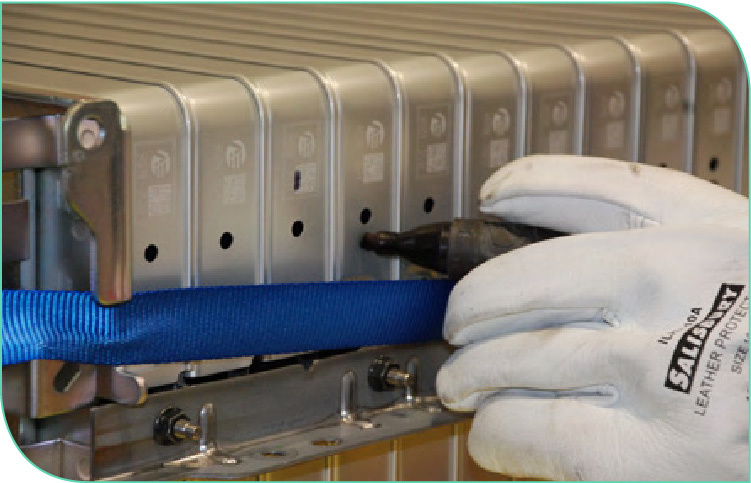
7. Remove the high voltage harness connectors for the bus bar and the battery junction box.
8. Disconnect the cell voltage monitor harness from the communication harness connectors located at the rear of the module pack. Cover all the harness connectors with insulating tape.
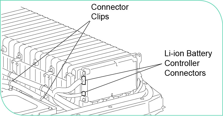
9. Remove the connector clips for the communication harness from the harness brackets, and then disconnect the communication harness from the Li-ion Battery Controller (LBC).
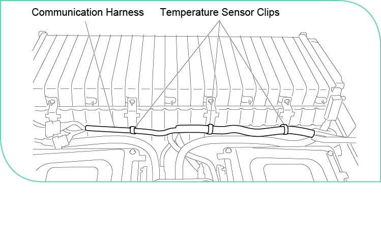
10. Remove the rear module pack temperature sensor clips from the bracket for the LBC.
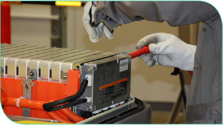
11. Remove the LBC along with the mounting bracket. Then, disconnect the four harness connectors from the bottom of the LBC. Cover all the harness connectors with insulating tape.
12. Mark the locations on the module pack where the temperature sensors go, the direction of the harness clips, and where the harness clips go using a permanent marker.
Then, disconnect the harness clip brackets that hold the communication harness and the temperature sensor harness connector located to the left/rear module bracket.
13. Remove the temp sensor harness and set aside.
14. Remove the vehicle communication harness connector from the rear module stack and set aside.
15. Open the left and right high voltage cable covers at each end of the rear module pack, and then disconnect the cables from the module stack. Cover all the harness connectors with insulating tape.
16. Remove the bolts from the front and rear module pack brackets to remove the rear module pack from the battery tray.
17. Use the woven slings from the tool kit and attach them to the corners of the rear module pack with the “D” rings. Use an appropriate engine lift to hoist the module pack from the battery and place it on the high voltage work table or a suitable bench.
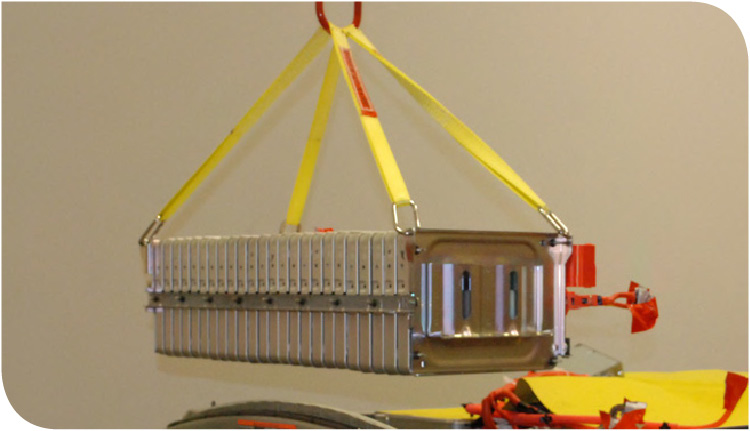
Helpful tip: Cut two pieces of 1”x 2” wood approximately 32 inches (81 cm), to place under the module pack. These strips will help support the module pack on top of your worktable by raising it up which will assist you during disassembly and assembly
Removing the Module From the Pack
1. Remove the four harness brackets from the front of the module pack.
2. Remove the center bus bar cover.
Note: Be careful when removing the cover so you don’t damage the bus bar or cover.
3. Remove the terminal bolts for the bus bar that connects modules 12 and 13.
Note: Removing the terminal bolts between modules 12 and 13 will reduce the voltage to 99 volts on either side of the open terminal.
4. Remove the terminal bolts for the bus bar that connects modules 6 and 7. Then, remove the terminal bolts for the bus bar that connects modules 18 and 19.
Note: Removing the terminal bolts between modules 18 and 19, will further reduce the potential voltage to less than 50 volts, on each side of the open terminal for the four module groups.
5. Remove the remaining terminal bolts from the bus bar, and then carefully remove the bus bar.
6. Remove the front mounting bracket from the battery pack.
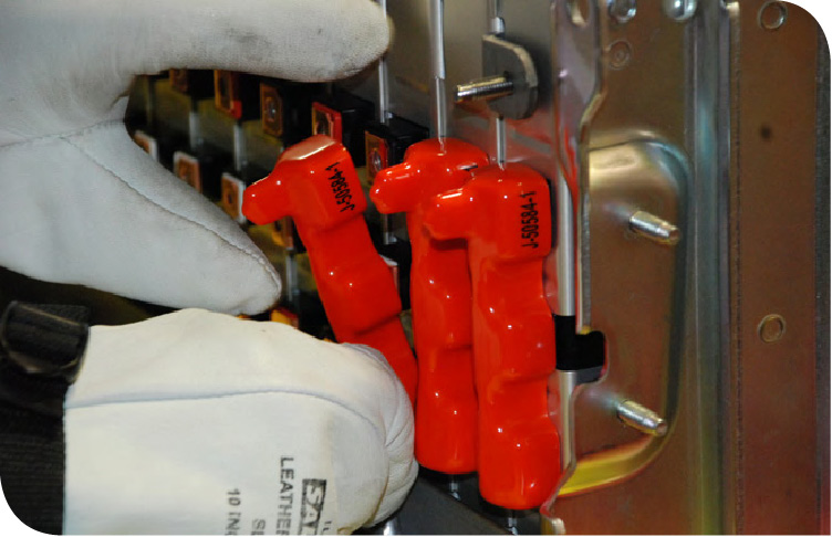
7. Cover the module terminals with J-50584-1 Protective Covers or use insulating tape.
8. Remove the rear mounting bracket from the battery pack.
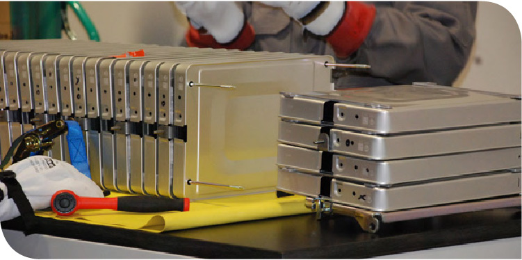
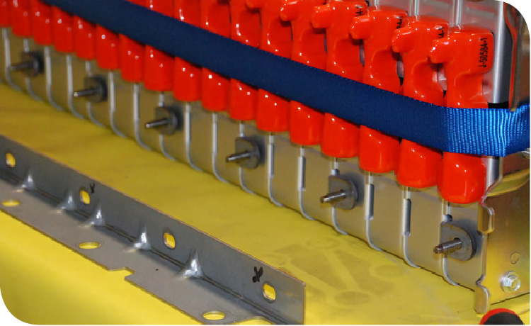
Helpful tip: Use the cargo strap to loosely hold the modules together. DO NOT over-tighten the strap, and wrap the buckles to prevent damaging the modules.
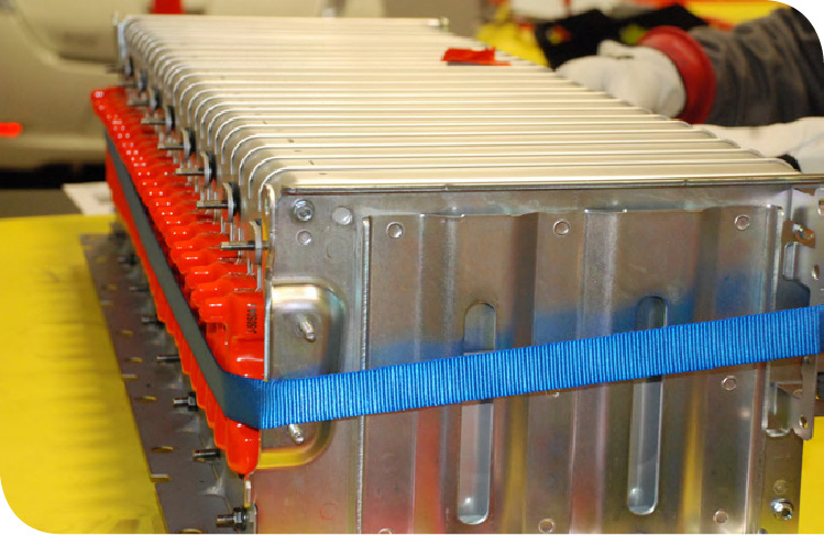
9. With the help of another person, loosen the through bolts carefully and remove the retainer nuts but not the through bolts. Pull the through bolt out of the module pack just enough to be able to remove the module to be replaced. Leave the through bolts inserted and in position to assist in alignment and reassembly.
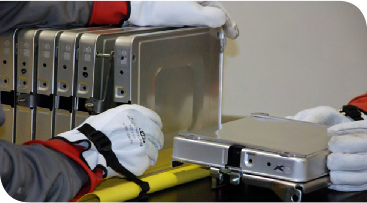
10. Loosen the cargo strap and remove the module. Note the position of the module spacer shims, as they differ depending on whether they’re for the support plate side, or the terminal side of the module stack.
Helpful tip: It’s a good idea to fashion a rack or holder to keep the modules in position as you remove them. This will help you to keep them from falling over or getting damaged, while you’re accessing the module that needs to be replaced.
Reassembly
Before replacing a module with a new module part, you’ll need to adjust the voltage of the new module to match the voltage level of the normal cells in the battery pack.
Helpful tip: The maximum cell voltage value in Data Monitor is used when replacing a module in the high voltage battery. The replacement module voltage will require charging or discharging to match the remaining cells in the high voltage battery.
Checking Adjustment Voltage Value with CONSULT
1. Power switch ON.
2. Select “DATA MONITOR of HV BAT”.
3. Check “MAXIMUM CELL VOLTAGE”.
4. Double the “MAXIMUM CELL VOLTAGE” and use that value as the module adjustment value.
Adjustment voltage value: MAXIMUM CELL VOLTAGE x 2
Example: 3.925 V (MAXIMUM CELL VOLTAGE) x 2 = 7.850 V (Adjustment voltage value)
Standard: Adjustment voltage value ± 10 mV
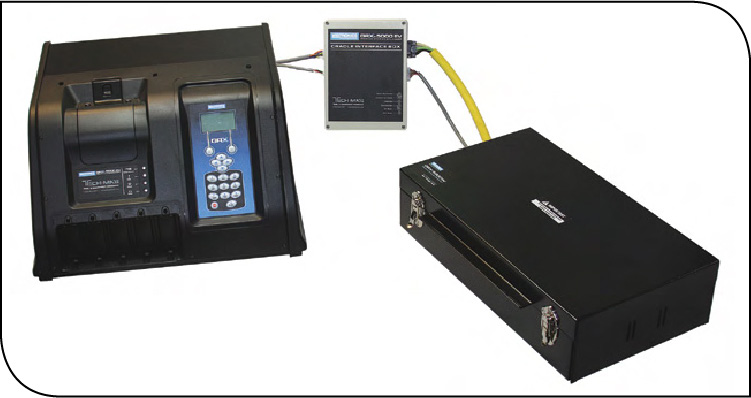
Use the Module Charge Balancer (J-50346) to adjust the replacement module to the target voltage. After module voltage adjustment, remove the module from the module charge balancer (J-50346), and use a circuit tester to check that the module voltage is within the specified range.
Installing the New Module
1. Install the new module into the battery pack. Pay close attention to the position of the module spacers on the modules when you place them into the pack. There are front and rear spacers.
2. With the help of another person, insert the through bolts through all the modules and end brackets. Install retainer nuts onto the through bolts and hand tighten them. Check that the modules are in alignment by measuring across the battery pack with a tape measure followed by another diagonal measurement from the opposite corners to ensure that the assembly is square.
3. Install the rear mounting bracket and hand tighten the retaining nuts.
4. Install the front mounting bracket and hand tighten the retaining nuts. Do not install the nuts for the four harness brackets at this time.
5. Remove the tape (or the protective covers) from the module terminals.
6. Install the bus bar to the module pack and hand tighten the terminal bolts. Be careful not to damage the covers or the bus bar. Tighten all bus bar terminal bolts to 5.5 Nm (0.56 kg-m, 49 in/lb).
• When bolts 1 – 16 have been tightened, install the left side bus bar cover.
• When bolts 17 – 32 have been tightened, install the right side bus bar cover.
• When bolts 33 – 48 have been tightened, install center bus bar cover
7. Tighten the retainer nuts on the through bolts to 9.6 N·m (0.98 kg-m, 85 in-lb).
Note: Tighten the retainer nuts to the through bolts to specification while checking alignment.
8. Tighten the front and rear mounting brackets retainer nuts to 9.9 N·m (1.0 kg-m, 88 in-lb).
9. Install and tighten the four harness brackets to 9.9 N·m (1.0 kg-m, 88 in-lb).
10. Reinstall the rear module pack into the battery assembly. Install the mounting bolts and tighten to 9.9 N·m (1.0 kg-m, 88 in-lb).
11. Reinstall the right and left high voltage cables, tighten the retaining nuts to 5.5 Nm (0.56 kg-m, 49 in/lb) and close the covers.
12. Reconnect the communication harness to the harness bracket on the front of the module pack. Connect the four harness connectors to the LBC and install to the bracket. Tighten the LBC mounting bolts to 5.5 Nm (0.56 kg-m, 49 in/lb). Connect the two connectors from the communication harness to the LBC.
13. Install the battery temp sensors. Connect the battery temp sensors to the communication harness connector and install the connector clip.
Reassembling the Battery Case
1. Ensure the battery case gasket is properly seated and install the upper battery case.
2. Install the service plug switch retainer plate and tighten retainer bolts to 5.5 Nm (0.56 kg-m, 49 in/lb).
3. Install the battery pack upper case cover bolts. Follow the tightening mounting sequence order as shown in the illustration below.
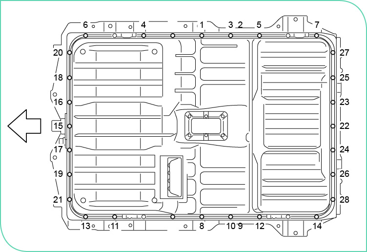
Install the M6 and M8 bolts in the proper locations in the upper battery cover:
M6 - 7.0 Nm (0.71 kg-m, 62 in/lb)
M8 - 17 Nm (1.7 kg-m, 13 in/lb)
Air Leak Inspection
After following the tightening mounting sequence procedure to reinstall the battery case cover, you need to check the case for seal leaks.
First, apply vinyl tape to seal the breather so that air does not enter it.
Insert the Service Disconnect Switch (SDSW) into the service plug switch retainer and lock.
Cover the high and low voltage connectors on the front of the battery case with insulating tape.
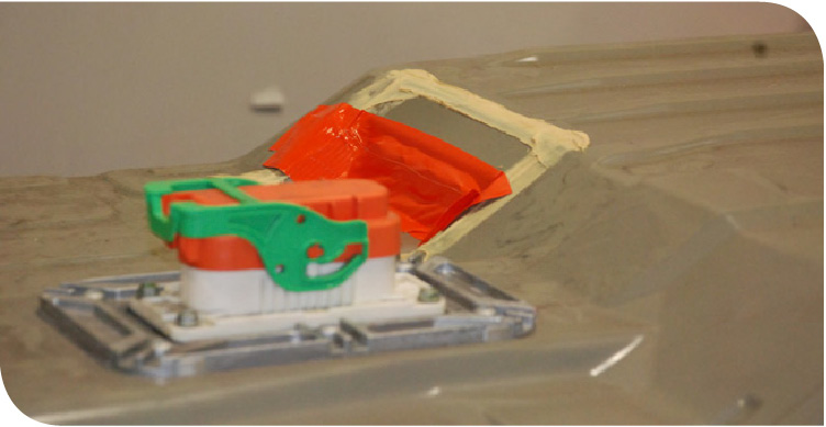
Remove the inspection port plug and install the pressure adapter fitting.
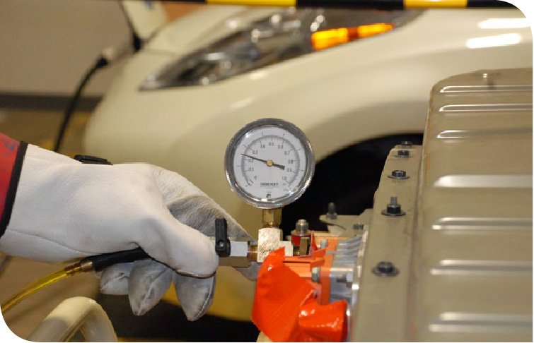
Connect an air pressure gauge and perform the air leak inspection by applying 1.6 kPa (0.0163 kg/cm2, 0.23 psi) of pressure inside the battery pack for approximately 1 minute. If the pressure drops below the limit value, use soapy water or the Stillman Engine Ear to and check for and isolate leakage points. If a leak is detected, inspect the battery cover, and seal, and perform any repairs necessary. Retighten the bolts to spec following the tightening sequence.
![]()
Caution: Never allow soapy water to contact the service plug or any connector terminals.
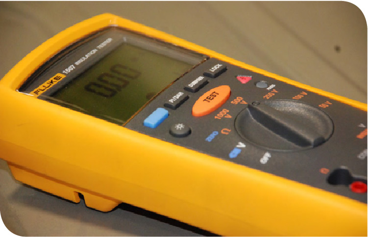
Electric Equipotential Test
After installing the battery pack cover successfully, perform an equipotential test by measuring the resistance between the ground bolt mating surface and the high voltage harness connector flange.
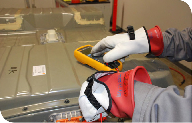
If the result deviates from the standard value of 0.1 ohms or less, check the following items and repair malfunctioning parts:
- Connection condition of ground bolts
- Rust on the mounting surface of ground bolts
- Paint, oil, and dust on the mounting surface of ground bolts
Fall 2011 Copyright© 2011 by Nissan North America, Inc.