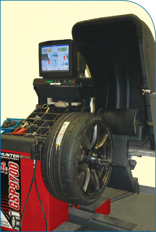
Tire/Wheel Assembly Balancing - Avoiding Vibration Problems
When diagnosing vehicle vibration conditions, you’ll probably want to first eliminate tires and wheels as a probable cause. Smooth rolling tires and wheels can be the difference. From there, it’s common to think that performing tire/wheel assembly balancing requires nothing more than the time it takes to chase weights, changing the weight angles, and/or just changing add-on weight amounts. But, keep in mind that changes in runout and force variation may all be produced by incorrect tire mounting, or, worn/damaged adapters on a balancer. Balancer equipment can’t identify mechanical mounting errors caused by incorrect mounting methods, and it won’t recognize worn or damaged mounting adapters. Mounting adapters must be inspected for excessive wear and should always be cleaned regularly to prevent dirt buildup from affecting the wheel balancer results. The machine is only as good as it’s calibration and its operator. The technician must correctly mount, then verify, the tire/wheel assembly is mounted correctly. This includes identifying the on-vehicle mounting method. Before checking for mechanical mounting errors, if you’re using Hunter GSP9700 equipment, always perform a Quick Cal-Check to verify accurate balancer calibration.
Balancer Calibration
Whether a wheel is mounted to a balancer with a cone, a collet, or a flange, it only takes a few thousandths of error mounting in the center to cause large errors at the rim. These errors can make the balance, runout, and road force measurements incorrect. To ensure you’ve eliminated setup errors, use the Quick Cal-Check feature to verify balancer calibration in seconds without the use of a reference wheel.
Centering Check may be built-in to the programmed sequence or selected manually.
When using the programmed sequence, Centering Check™ will pop up automatically once you’ve entered
the wheel dimensions.
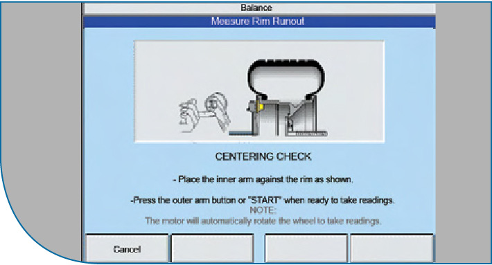
1. Place the inner data-set arm against the rim, and measure runout.
2. Rotate the wheel and position the valve stem at 12 o’clock, then press Enter Valve Stem.
3. Loosen and relocate the wheel and adapter from its original position and re-measure runout.
4. Then, reposition the valve stem at 12 o’clock once again, and press Enter Valve Stem.
5. If a problem is detected, the error screen is displayed. The screen will provide a checklist to help you repeat Centering Check™ to help you resolve the problem. If the wheel is properly centered, the Centering Quality Check Passed screen will display, and the system will proceed to the Balance screen.
To eliminate setup errors, use the Quick Cal-Check to verify balancer calibration in seconds without the use of a reference wheel.
Getting Started
Before you begin tire/wheel assembly balancing, you should always perform a road test to confirm the existence of the problem.
When you do this, you’ll also be warming-up the tires which will remove any temporary flat spotting. Drive the vehicle about 15mi (24km) to warm up the tires to operating temperature.
To increase tire/wheel assembly balancing accuracy, proper steps should be followed:
Setup
- Set the tire pressure to the tire placard pressure.
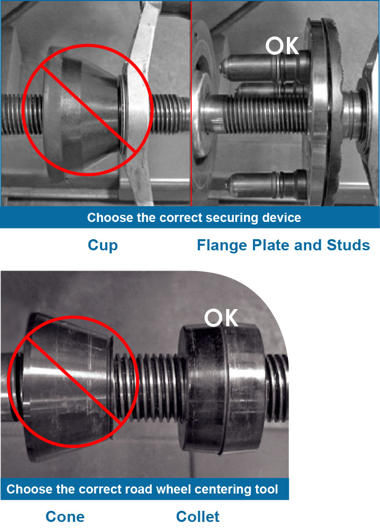
- Choose the appropriate wheel centering balancer collets and flange plate.
- Choose the correct road wheel centering tool.
- Determine the road wheel-to-collet contact area, for proper centering.
- Choose the correct securing device.
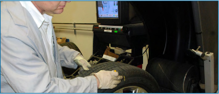
- Properly mount the tire/wheel assembly to the wheel balancer
- Ensure the tire and wheels are free of debris.
Wheel Centering Quick Check
Run the tire/wheel assembly on the wheel balancer in the “non-round-off” mode and record the imbalance measurements.
- Mark the location(s) where the weight(s) are requested.
Note: Center Check™ may be used with either a “bare rim” or a “rim with tire assembly.” The CenterCheck™ feature can be used to automatically identify any centering errors and confirm if the wheel is centered on the balancer.
Loosen the wing nut while keeping the tire/wheel assembly from turning on the balancer shaft.
Rotate the tire/wheel assembly 180 degrees on the balancer shaft, and then secure it with the wing nut.
Note: Slowly rolling the wheel toward you helps improve accurate wheel centering since the wheel is allowed to roll up the taper of the cone.
Run the tire/wheel assembly again.
- The imbalance values should be within ¼oz (7g) of the values of the first test.
- The weight(s) should be located within 2-3in (50-75mm) of the locations of the first test.
Uniformity Checks
- Perform a uniformity check on tire/wheel assembly.
- Mark the high spot on the tire.
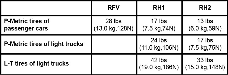
- Write the final Radial Force Variation (RFV) reading on the tire.
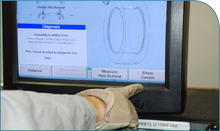
Note: These are guidelines only. Some vehicles may require a lower uniformity value to correct vibration conditions.
Tips on Mounting Wheels to Vehicle
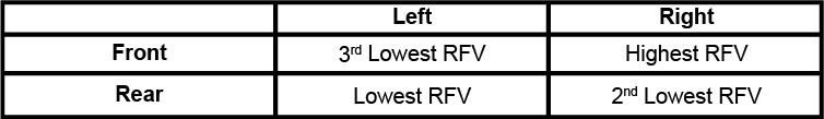
Install tires from lowest to highest RFV. Refer to the tables below for the recommended tire/install position:
Car/SUV
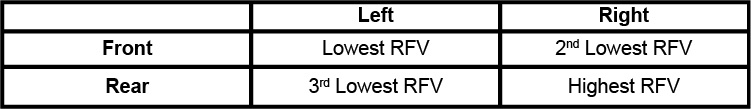
To Correct Truck Steering Shimmy Conditions
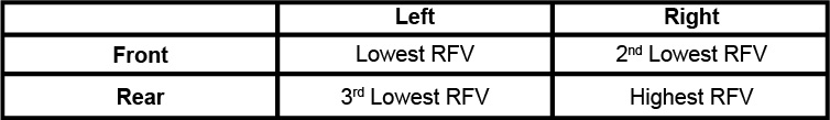
To Correct Truck Body and/or Truck Bed Vibration Conditions
Note: With the vehicle on a lift, always make sure the high spot marking is UP, before hand-tightening and then torquing the lug nuts to specification. With the vehicle on the ground: After hand tightening the lug nuts always make sure the high spot marking is DOWN before torquing to specification.
Lug Nut Torque
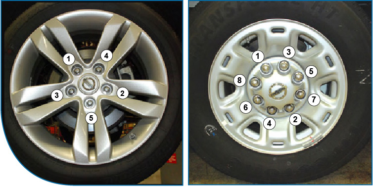
Follow a star pattern when tightening the lug nuts, and torque them to the recommended specification for the vehicle.
Finishing Up
The final step should always include a road test of the vehicle after performing the tire/wheel balancing procedures to confirm there isn’t a tire/wheel assembly vibration condition present.
In the event a tire is changed, RH1 should be re-checked (due to a potential mounting issue or aftermarket tire quality). If uniformity is NG, then the bead should be broken, re-soaped and mounted. If uniformity is still NG, tire should be rotated 180 degrees on the wheel.

Fall 2011 Copyright© 2011 by Nissan North America, Inc.