ICC Sensor Alignment and Aiming
2013 Infiniti JX35 vehicles can be equipped with a new type of Intelligent Cruise Control (ICC) system. This system incorporates a new ICC Sensor which requires an essential service tool kit 1-20-2721-1-IF to perform aiming adjustment service.
For the driver assistance systems to function properly, the new radar sensor must be precisely aligned using the ICC aligner. However, if the ICC sensor is far out of adjustment, has been removed or a new part is installed; use the J-51093 ICC Sensor Alignment Tool to verify the radar unit is at least level before performing the ICC Sensor aiming adjustment procedure. The ICC sensor aiming process outputs millimeter radar waves and then calculates the displacement adjustment in radar direction using CONSULT-III plus Work Support.
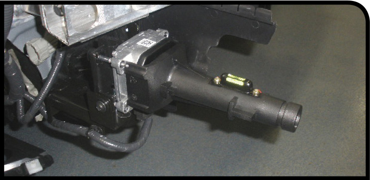
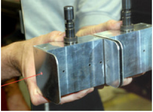
Attach the J-51093 Sensor Alignment Tool to the ICC Sensor to ensure the sensor is level.
Preparation
ICC Sensor aiming is a simple process. If you can align a vehicle, you can do the procedure!
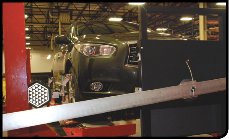
Place the vehicle on a camera based Hunter wheel aligner machine.*
A 4-wheel vehicle alignment must always be performed before proceeding with the ICC Sensor alignment and aiming procedure.
1. Adjust pressure in all tires to the specified cold tire pressure value.
2. Empty the vehicle. (Remove any luggage from the passenger compartment and cargo area.)
3. Shift the selector lever to “P” position, and release the parking brake.
4. Fully fill the fuel tank, and then check that the coolant and oils are filled up to correct level.
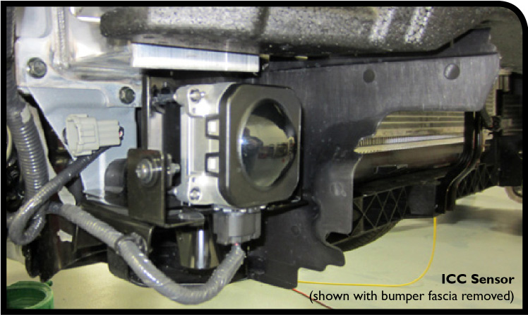
5. Clean off the fascia in front of the ICC Sensor.
NOTE: The ICC Sensor is located behind the fascia so it should not r equire any cleaning. Whenever the sensor is removed or replaced, verify the rough level adjustment of the radar unit with the Sensor Alignment Tool before performing the ICC Sensor aiming procedure.
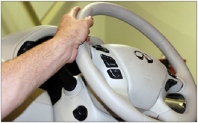
* IMPORTANT NOTE: The ICC Alignment Kit will function manually without a wheel aligner using a Hunter self-centering wheel adapter. Perform a 4-wheel alignment and then center the steering wheel before beginning the ICC Sensor alignment and aiming procedure.
Aiming Procedure
Positioning the Target Board
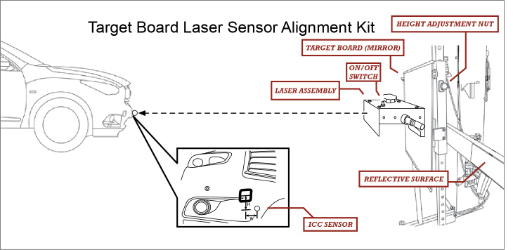
1. Visually position the center of the ICC target board approximately 3 feet in front of the vehicle.
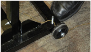
NOTE: The initial ICC target board setting must be in the (vertical) position. Extend the tool chain from the target board to the ICC Sensor location. You can use the brass part of the chain to measure out approximately 3 feet.
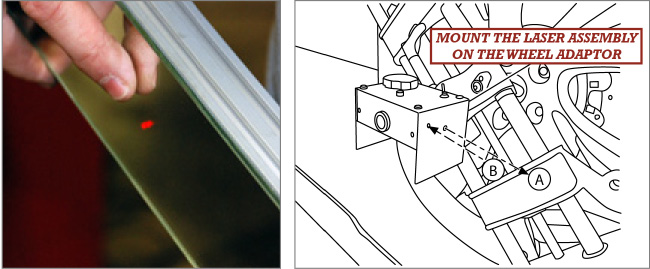
Tech Tips: Use the laser assembly to position and adjust the target board.
a. Place one side of the laser assembly flush against the center of the ICC target board mirror to assist in the positioning.
b. Turn the laser assembly ON allowing the laser beam to emit from the laser assembly toward the center of the ICC sensor.
c. Move the ICC target board as necessary so that center of ICC target board aligns with center of ICC sensor.
d. Adjust the height of the ICC target board using the adjustable nuts lifting or lowering to achieve the proper height.
2. Align the mirror precisely to the vehicle thrust angle in a straight-ahead position. This is accomplished by using the laser assembly wheel-mounted adapter, stationary target and the target board.
3. Install Laser Assembly
- Install the wheel adapter on the right front wheel.
- Mount the laser assembly to the wheel adapter as shown in the illustration.
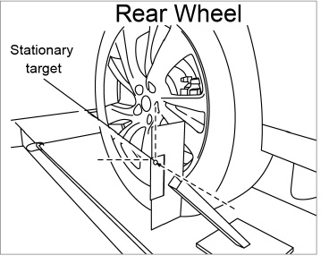
4. Install Stationary Target Place the stationary target next to the right rear wheel as shown in the illustration.
5. Target Board Final Setting Extend the machined arm of the ICC target board placing the reflective surface to the right front side of the vehicle.
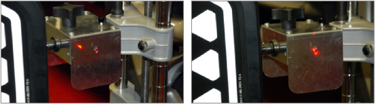
Turn the laser assembly ON. The front laser signal (A) will be emitted toward the reflective surface on the target board arm and the rear laser signal (B) will be emitted toward the stationary target.
6. Confirm that the vehicle is pointing straight ahead and the ICC Sensor is level and aligned precisely with the target board, laser assembly and the stationary target.
a. Rotate or slowly pivot the ICC target board stand to achieve the necessary horizontal adjustment.
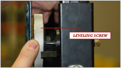
b. Adjust the ICC target board leveling screw to achieve the necessary vertical position adjustment.
NOTE:
- Horizontal adjustment of the laser assembly can be assisted by slowly turning the steering wheel. Pivoting the entire stand as necessary will also help to reflect the laser back to the laser assembly..
- Vertical adjustment of the laser assembly can be assisted by rotating the leveling screw around its axis until the two lasers meet.
Adjust the laser beam as necessary until the two lasers match. Turn the laser assembly OFF when done.
7. Use CONSULT Work Support to Check and Adjust ICC Sensor Alignment.
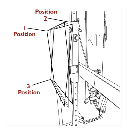
Check displacement direction, and perform adjustment as necessary. Perform the adjustment determination for all three different ICC target board positions. Follow all the instructions exactly as requested in CONSULT:
- Position 1, with 2° top tilted toward the vehicle.
- Position 2, vertical.
- Position 3, with 2° top tilted away from the vehicle.
Use CONSULT To Check and Adjust Radar Alignment
1. Push ignition switch in the ON position.
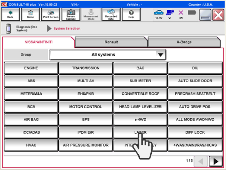
2. Connect CONSULT and select “LASER/RADAR,” then “Work Support.”
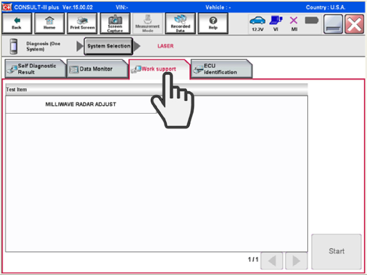
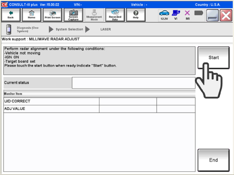
3. Select “RADAR Alignment” and click Start.
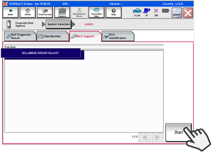
4. Select “Radar Adjust”, and then “start” after the “RADAR Adjust” screen is displayed.
NOTE: If an Error Screen appears within approximately 10 seconds after “RADAR Adjust” is selected, the following causes are possible:
- Radar Adjust is selected, but the ICC target board is not installed in the correct position.
- Adequate space is not secured around the ICC target board.
- The radar alignment procedure exceeds its proper installation range.
- Deformation of vehicle body.
- Deformation of unit.
- Deformation of bracket.
- The area is not suitable for the adjustment work.
- Right front side of fascia (ICC sensor view) or sensor is not clean.
- The ICC system warning lamp illuminates.
- The vehicle has low battery voltage
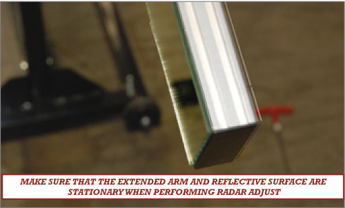
- The extended arm and mirror is not stationary.
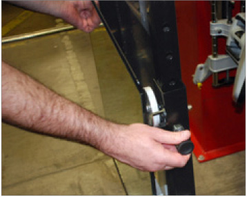
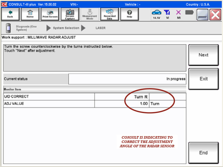
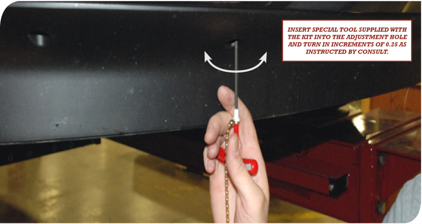
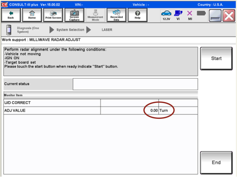
You will be prompted with specific instructions to perform alignment of the sensor, (if necessary) by turning the sensor adjusting screw with the adjustment tool by a certain number of turns in increments of 0.25 in the direction indicated by CONSULT.
![]()
Be careful not to cover the right front side of the fascia (ICC Sensor view) with a hand or any other body part during adjustment, as this may result in incorrect radar adjust values.
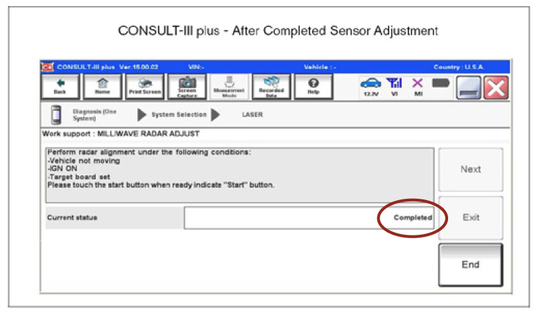
6. CONSULT will not update the ADJ VALUE while you are turning the adjust tool. Recheck the ADJ VALUE with CONSULT by performing the Radar Alignment steps after each incremental correction adjustment. Confirm proper radar alignment by following CONSULT steps until it shows "ADJ VALUE" to be 0.00 turn. CONSULT will display a Completed message.
Note: Always perform the ICC system action test to confirm that the ICC system operates normally after replacing the ICC sensor or repairing any ICC system malfunction.