
Correct wheel alignment plays a huge part in a customer’s positive driving experience. Having it dialed in correctly is essential to proper vehicle handling, safety, maximum fuel economy and tire life. Webster’s dictionary defines the term “alignment” as “the proper positioning or state of adjustment of parts (as of a mechanical or electronic device) in relation to each other.” Correct alignment of a vehicle’s suspension means positioning the wheels to allow the vehicle to track smoothly. If a vehicle’s tires are rolling freely and evenly without pulling or scuffing down the road, it will help the vehicle to drive straight while minimizing steering effort. Definitely the way to go!
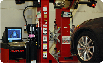
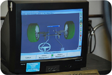
With today’s fully computerized alignment machines, knowing all the angles of alignment is not necessary, right? Well, as it is with many mechanical things, it helps to know what is going on. So for the technician who is new to wheel alignments or for the one who wants to refresh his or her basic knowledge, this article will concentrate on the eight different fundamental angles that fall under the heading of wheel alignment. Some of the angles we list are a part of the chassis/suspension design known as fixed angles and would only be off-specification if something were bent or broken. Other angles are adjustable (depending on the vehicle’s design). So, let us round up the usual (and not-so-usual) suspects when wheels are pointed in the wrong direction.
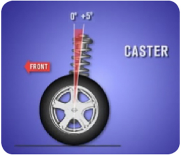
CASTER
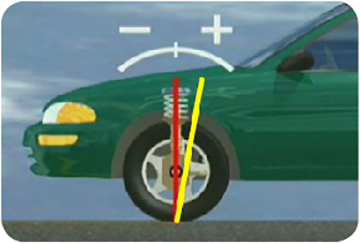
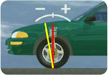
Caster is defined as the forward or rearward tilt of the projected steering axis from true vertical as viewed from the side. Caster is sometimes called a directional control angle because it can determine whether the vehicle travels straight or if it drifts (vehicle takes a lead to a direction other than straight) or pulls (steering wheel tries to turn) to the right or the left. However, as a rule, caster will not cause tires to wear. Unless the chassis/suspension is radically out-of specification, it will not affect tire life.
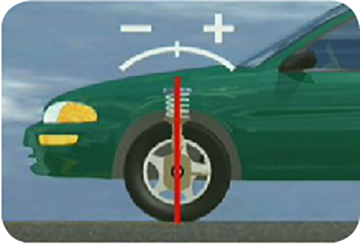
Caster is the measurement of the forward or backward tilt of the steering knuckle (spindle support) arm when viewed from the side of the vehicle. The caster setting controls where the tires touch the road in relationship to an imaginary centerline drawn through the spindle support. Caster is measured in degrees (positive or negative), starting at the true vertical (plumb line) of the steering knuckle (spindle support) arm.
Positive, Negative, & Cross Caster
A positive caster reading means the top of the steering knuckle is tilted toward the rear of the vehicle. Great examples of this are bicycle (or motorcycle) forks, which sometimes have radically positive caster. The bike frame’s load is carried by the fork steering knuckle, but the wheel axle is way out ahead. Vehicles usually have some positive caster specified since this promotes directional stability. That angle shifts the actual load out ahead of the axle, increasing stability. It also helps with positive steering wheel return.
With a high amount of positive caster, the camber changes that occur, especially at low speeds in tight turns, will cause the tires to show wear on their shoulders. In high speed cornering, the vehicle tends to continue straight ahead when the steering is initially turned. Due to this and the amount of camber change that takes place when a spindle travels through its arc of travel, the shoulders of the tires on a vehicle may scrub and wear. This can result in vehicle wander or lack of directional stability. Not desirable traits!
Negative caster tilts the top of the steering knuckle toward the front of the vehicle. A great example of this is a shopping cart’s front casters. The caster pivot point carries the load, but when the cart is pushed, the axle wants to swivel to behind the pivot point. Having the axle behind the load makes it easier to steer the wheels, but the wheels will tend to swivel and follow the irregular surfaces and imperfections in the road (like on a vehicle chassis).
IMPORTANT NOTE: A vehicle will always lead or drift to the side that has the least caster, side to side. This left-to-right caster relationship is called cross caster.
Since a chassis will always drift to the side that has the least caster, you would think that caster, whatever the specified range, should always be set at exactly the same specification on both sides of the chassis, right? Not necessarily so! Cross caster can be used to offset the effect of road crown. Road crown is the normal slope of the road toward the outer edge of the road surface. Most road surfaces angle downward from the center of the road to divert rainwater (sometimes to the right, depending on the area, and some areas more than others do). A chassis set at zero cross caster may drive straight down a flat road but tend to drift down a road crown. However, kick in a slight amount of extra negative caster on the opposite side of the drift and the drift is canceled out. This is a pretty cool trick for some of you front-end experts out there. Remember to always stay within the adjustment range specified for the chassis you are working on so that the vehicle behaves as designed for common road profiles.
CAMBER
Camber is the inward or outward tilt of a wheel when viewed from the front of the car. A wheel tilting outward at the top has positive camber, and a wheel tilting inward at the top has negative camber. Camber is a tire-wearing angle, appearing as smooth (not feathered) wear. If there is too much positive camber, the wear will be on the tire’s outer edge. If there is too much negative camber, it will be on the inside edge. Negative and positive camber are measured from the true vertical (plumb line) and are measured in degrees. If the wheels are aligned at true vertical, camber is zero (neutral). Camber can also be a directional control angle if there is too much of it. A chassis will lead or drift to the side that has the most positive camber. A crowned road means that the outside/right hand side of the lane is lower than the left side of the lane. However, camber should never be adjusted to compensate for road crown since uneven and excessive tire wear will result if too much camber (positive or negative) is set.
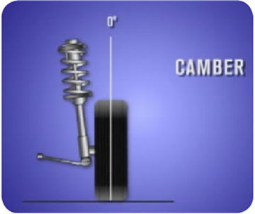
NOTE: Vehicles with wide tires are very sensitive to the camber being off.
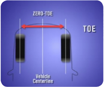
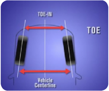
TOE
Toe is definitely the easiest of all to visualize. If a pair of wheels on the same axle are closer together at the front than at the rear, they are toed-in. If they are closer at the back than at the front, they are toed-out. If the wheels are exactly parallel, they are at zero toe. It is the position of the wheel in relation to the centerline of the chassis when viewed from the top. The amount of toe can be expressed in linear measurements (fractions of an inch or millimeters) or degrees as the angle to which the wheels are not parallel. Toe is an angle that can really tear up tires. Excessive toe results in tire wear and drag on the vehicle. If the toe setting is incorrect, the tires scuff or skid sideways as the vehicle is moving ahead. Excessive toe wear is sometimes described as feathering since the wear pattern is a serrated (not smooth) wear across the face of the tire. Slight feathering can be felt by hand when sliding the palm across the tread side to side. It feels rough one way and smooth the other.
NOTE: Only 3 millimeters of improper toe cause tire wear equal to dragging a tire sideways 28 feet for every mile traveled.
Toe is one angle that tends to be generalized in a one-size-fits-all mentality. But, some chassis, like our 370Z, are very sensitive to having exactly the right settings. Do not assume anything and always check the applicable Nissan or Infiniti Electronic Service Manual (ESM) for the exact specifications.
Caster, camber and toe are definitely the top three alignable adjustment angles you need to understand in order to get a chassis pointed straight. But not to be left out, there are other factors in the alignment equation. The following measurements are almost never adjustable.
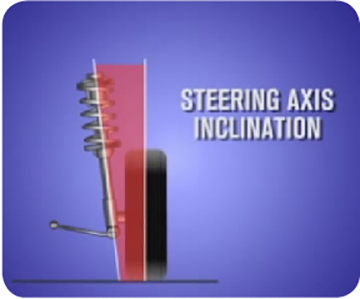
STEERING AXIS INCLINATION (and scrub radius)
Steering axis inclination (SAI) is the angle measured between true vertical and the inward tilt of the steering knuckle, king pin or McPherson strut tube. SAI is typically not adjustable, but any deviation from specification can indicate vehicle damage. It is designed into the suspension system, so if the angle is not correct, it is necessary to diagnose and possibly replace bent parts, like spindles or struts, to correct the situation. SAI is always an inward tilt regardless if the wheel has positive or negative camber.
SAI has three functions:
- Helps the vehicle return to the straight position after a turn.
- Helps the vehicle track straight ahead.
- Gives the vehicle good directional stability with less positive caster designed in.
The spindle (or axle) is horizontal with the wheels pointed straight ahead. With this inboard tilt designed into the steering knuckle or strut, as the steering turns, the axle/spindle will try to move closer to the ground. Because the spindle cannot move any closer due to the tire, the car must lift. The effect of SAI, coupled with the vehicle’s own weight, helps re-center the steering from turns. SAI also helps reduce steering effort by reducing the scrub radius.
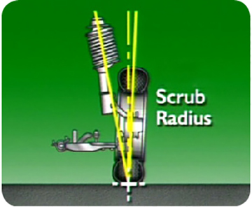
Scrub radius is a factor of steering axis inclination. It is the distance (at the road surface) between the true vertical at the center of the tire tread and the steering axis pivot centerline. The intersection of the steering axis and centerline pivot point is usually slightly below the road. When the intersection is below the surface of the road, this is positive scrub radius. The distance below the surface of the road determines the amount of scrub radius. Conversely, when the lines intersect above the road, negative scrub radius is present. When a vehicle has been changed into lower height tires and wheels with increased positive offset, it causes a big increase in scrub radius. This may result in harder steering and a tendency for the wheels to wander or shimmy.
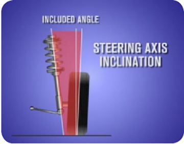
INCLUDED ANGLE
Included Angle is simply the combination of SAI plus camber. For example, on a chassis with 10º of SAI and 1º of positive camber, the included angle is 11º. Alone, this angle does not mean much. But back in the day, some alignment machines measured included angle, not SAI. To get SAI, you had to do the math, deducting camber from the included angle.
TURNING RADIUS/TOE-OUT ON TURNS
Toe-out on turns, also called turning radius, is the amount the front wheels toe-out when turning corners. As the vehicle goes around a turn, the inside tire must turn more sharply and in a smaller radius (circle) than the outside tire to maintain good traction and low tire wear. Steering systems are designed to allow the vehicle’s wheels to move through different arcs of travel and turn different amounts. Turning radius/toe-out is not an adjustable angle; it is controlled by the built-in angle of the steering arms. If the turning radius is incorrect, it indicates damaged or bent steering parts.
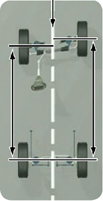
TRACKING (thrust line or thrust angle)
Incorrect tracking (or excessive thrust angle) happens when the centerline of the rear tires is not parallel to the chassis centerline. This can also be caused when the rear wheel centerlines are not equal side to side. Have you ever seen a car going down the road and the rear tires are not tracking in line with the fronts? That is too much thrust angle. As you can imagine, zero thrust angle is ideal for the best fuel economy and tire wear. A common culprit here is incorrect rear toe settings, but bent parts can also be the cause.
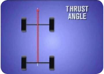
If the thrust angle is not zero, it can cause the vehicle to handle differently when turning as the driver compensates for the thrust angle or tries to drive straight down the road.
CLEAR-VISION
Clear-vision has become a generic term describing if the steering wheel is properly centered or leveled during alignment adjustment. Clear-vision can be controlled from the front toe settings. A good practice is to set the front toe with the vehicle running so that the power steering system is pressurized. Make sure the steering wheel is not crooked and is adjusted to the straight ahead position to be certain there will not be a spoke blocking the driver’s view. Then adjust the left and right tie rods so that the total toe is equally divided between both sides.
SETBACK
Setback is just as it sounds; the amount by which one front wheel is further back from the front of the vehicle than the other. Setback should usually be around zero, but some vehicles have asymmetrical suspensions by design. Positive setback indicates that the right front wheel is setback further than the left. Negative setback refers to the left front wheel being further back than the right.
Setback is measured with both wheels straight ahead and is used as a diagnostic angle along with caster to identify chassis misalignment or a larger problem that was missed when measuring a collision-damaged vehicle. The presence of setback can also cause differences in toe-out on turn angle readings side to side. A setback condition can possibly occur if the vehicle hit a pothole or curb or was involved in a collision that affected the vehicle’s undercarriage.
PRELIMINARY CHECKS
Proper pre-flight checks are critical for airplanes. And to keep your customers “flying straight,” it is essential, before beginning a wheel alignment, to check the following:
1. Tires for wear or improper air pressure.
2. Road wheels for runout.
3. Wheel bearing axial end play.
4. Ball joint axial end play of compression rod, upper link and steering knuckle.
5. Shock absorber operation.
6. Each mounting part of the axle and suspension for looseness and deformation.
7. Each link, rod and member for cracks, deformation and other damage.
8. Vehicle posture (height, rake and side to side).
NOTE: Always measure wheel alignment under unladen conditions. This means everything in place but the driver. The vehicle’s fuel, engine coolant and all lubricants are full. In addition, the spare tire, jack tools and floor mats should be installed in their designated locations.
Remember, our customer’s appreciation of his or her vehicle’s drivability is greatly affected by its wheel alignment! So, if a customer happens to complain about the extra time it takes to “get it right,” help them to be patient by reassuring them and communicating that correct wheel alignment will improve his or her driving satisfaction. Keeping his or her wheels aligned can help prevent tire wear, increase his or her fuel mileage by reducing road friction and improve the vehicle’s handling.