
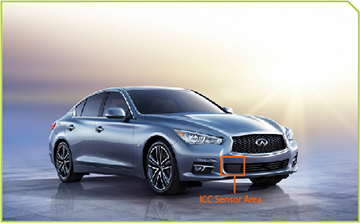
The Q50 with Intelligent Cruise Control utilizes an ICC Sensor that must be aligned using special service tools and special procedures.
- Hunter Self-centering Wheel Adaptor
- ICC Alignment Kit (1-20-2721-1-IF)
- Aluminum ICC Target Adapter (J-50808) (Infiniti Only)
Suggested Tool
- Hunter Alignment Rack
IMPORTANT NOTES:
- Perform a 4-wheel alignment and then center the steering wheel before beginning the ICC Sensor alignment and aiming procedure.
- Always perform the radar alignment after removing and installing or replacing the ICC Sensor.
Procedures Overview
Performing ICC Sensor alignment on the Q50 vehicle is similar to the procedure for the QX60 vehicle with some exceptions.
1. Use the ICC Alignment Kit (1-20-2721-1-IF) target board with the new essential Aluminum ICC Target Adapter (J-50808) placed over the mirror. Set the target board at the correct position in front of the vehicle, staging it on the Hunter Aligner.
2. Set the radar alignment mode (“MILLIWAVE RADAR ADJUST” on “Work support”) with CONSULT to perform the adjustment. The ICC radar sensor on the Q50 will then adjust itself and does not require mechanical adjustment.
3. Perform the ICC System Active Test to confirm that the ICC system operates normally.
Advance Preparation for ICC Sensor Alignment
Make sure you prepare the vehicle before performing the ICC Sensor aiming procedure.
1. Adjust all tire pressures to the specified values.
2. Empty the vehicle. (Remove any luggage from the passenger compartment, trunk, etc.)
3. Shift the selector lever to the P (Park) position and release the parking brake.
4. Fully fill the fuel tank and then check that the coolant and all other fluids are filled up to the correct levels.
5. Clean the ICC Sensor area of the front bumper grille.
Setting the Target Board When Using the Hunter Alignment Rack
1. Perform the Advance Preparation for Radar Alignment.
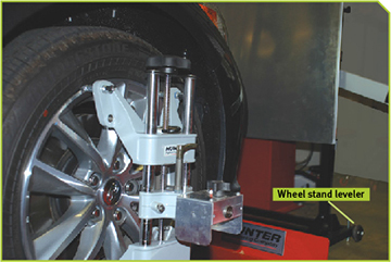
2. Position the vehicle on the Hunter Alignment Rack.
NOTE: Perform a 4-wheel thrust alignment and then center the steering wheel before beginning the ICC Sensor alignment and aiming procedure.
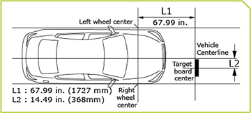
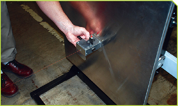
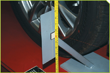
3. Hang a string with a plumb tool from the fender so it passes through the center of the right and left front wheels. Next, mark the center points of the front wheels on tape placed on the floor of the Alignment Rack runway.
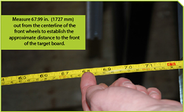
4. Measure 67.99 in. (1727 mm) out from the centerline of the front wheels to establish the correct distance from the vehicle to the front of the target board.
5. To quickly center the Target board in front to of the sensor:
- Place the Aluminum ICC Target Adapter (J-50808) over the mirror.
- Hold the laser against the center point mark on the aluminum target board.
- Turn the laser on, and shine it on the ICC sensor location at the bumper.
Adjust the ICC Target board until it is centered when shining the laser right on the ICC sensor location at the bumper fascia.
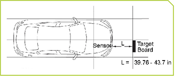
NOTE: Measure from the ICC Sensor location at the bumper fascia to the front of the target board. Make sure that it is within the range of 39.76 – 43.7 in. (1009.9 – 1110.0 mm) from the bumper fascia (at the sensor).
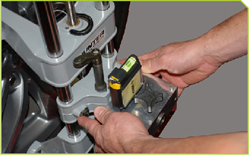
Mount the Wheel Adaptor/Tire Clamp Assembly to the Right Front Wheel
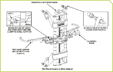
1. Mount the laser from the kit onto the Wheel Adaptor/Tire Clamp Assembly and use a bubble level to make sure it is horizontally level.
2. Adjust the mirror arm of the ICC target board so it is level with the laser emitter on the wheel adaptor.
3. Adjust the target board until you can reflect the laser beam back into the laser emitter.
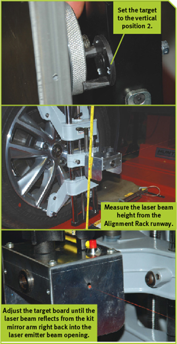
4. Place the rear target stand reflector in front of the right rear wheel.
NOTE: The laser beam should be horizontal. Measure to see that the beam hits the target stand at the same measurement from the Alignment Rack runway.
When vehicle thrust angle and target is set, proceed with CONSULT to perform the ICC Sensor adjustment procedure.
ICC Radar Alignment Adjustment with CONSULT-III plus
![]()
The vehicle’s battery voltage must not fall below 12 volts during the whole radar alignment procedure. Failure to maintain adequate battery voltage will cause the test to fail. If this happens, you will have to restart the radar alignment process.
The radar alignment is performed automatically using C-III plus without any manual adjustment.
![]()
Perform all necessary work for radar alignment until the adjustment completes as shown in the procedure. If the procedure does not complete, the ICC system is inoperable.
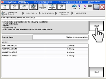
1. Start the engine or set the vehicle to READY (Hybrid Model).
2. Connect CONSULT and select “Work support” of “LASER/RADAR.”
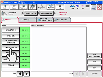
3. Select “MILLIWAVE RADAR ADJUST” after the “Work support” screen is displayed.
NOTE: Confirm the following items:
- The target should be accurately placed. If the target is not placed accurately, C-III plus will display: “Alignment condition is not ready.”
- Do not sit in the vehicle during radar alignment. Remain outside and away from the vehicle when performing the alignment with C-III plus to ensure the vehicle is not bumped or moved during the aiming procedure.
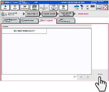
4. Select “Start” after the “MILLIWAVE RADAR ADJUST” screen is displayed.
5. Select “Start” after the preparation information is displayed.
6. Select “Next” after the “Starting alignment.” screen is displayed.
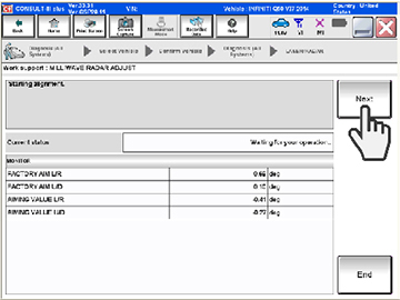
NOTE: If the radar is in alignment at this time, “Alignment in progress” is displayed. It may take several tens of seconds until the result is displayed.
7. Confirm the displayed item.
“Alignment completed”.
8. Confirm displayed values.
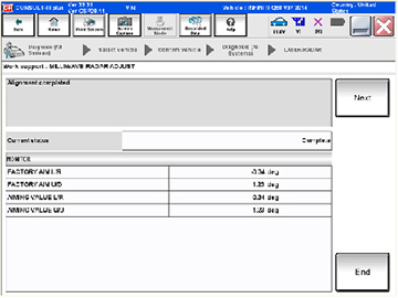
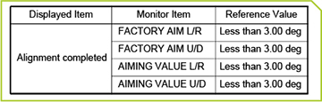
9. Select “End” to complete the alignment procedure if all values displayed are within 3.00 degrees of each other.
NOTE: Perform an ICC System Action Test to ensure that the ICC system operates normally after completing the ICC radar sensor alignment, replacing the ICC Sensor or resolving an ICC system malfunction.
IMPORTANT NOTE:
- Always drive safely when performing the action test.
- Turn the Distance Control Assist (DCA) system to OFF when performing the action test.