The electronic controlled powertrain has been redesigned to improve its characteristics and balance.
The redesigned power train has been reduced in size by 30% and total power train weight by 10%. The direct benefit of this weight reduction is increased energy efficiency. The new power train has been given improvements in responsiveness and drivability, such as no loss in acceleration performance, increased utility and reduced noise.
Charging and Distribution
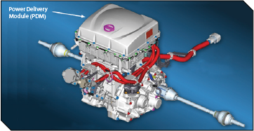
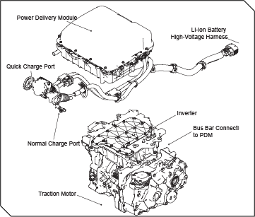
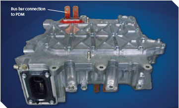
The ePower Train charging and power distribution components have also been integrated into a single unit called the Power Delivery Module (PDM). The PDM is installed to the upper part of drive motor. This new unit combines the functions of the DC/DC Converter, Junction Box, and Onboard charger. All of the high-voltage harnesses except one are connected to the PDM.
The on-board charger uses a 2-converter system which consists of the PFC circuit and the DC/DC converter. It improves charging efficiency, charge level accuracy, and the service life of the Li-ion battery. The PDM judges whether external power supply is 100 V or 200 V, and automatically switches to charging that is appropriate for the power supply.
The DC/DC converter charges the auxiliary 12V battery according to the VCM command.
PDM Service Procedures
If any of the high-voltage harnesses connected to the PDM are damaged or faulty, removal of the PDM from the vehicle is required to replace the harness.
After installing the PDM in the vehicle, check the sealing of the PDM to the inverter by performing an air-tight test. The PDM must be properly sealed to prevent moisture intrusion.
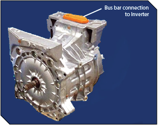
Utilizing bus bar connections has allowed the inverter to be mounted directly to the traction motor, and the PDM to be mounted directly to the Inverter.
Traction Motor Inverter
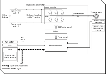
The traction motor inverter is a device which converts DC power from the Li-ion battery to AC power, and drives the traction motor accurately based on resolver detection signal and current sensor detection signal. The traction motor inverter applies AC power to the traction motor according to the target motor torque signal calculated by VCM in order to generate drive force.
Control of the traction motor and control of EV system CAN communication with other control modules is actually performed by the motor controller. However, because the motor controller is installed inside the traction motor inverter, the motor controller is referred to as the traction motor inverter.
During deceleration, the traction motor is used as a generator. It converts kinetic energy generated by rotary motion of the tires to electric energy and charges the Li-ion battery.
Inverter
The Inverter in the 2013 LEAF® is lighter and more compact. Since it receives power from the PDM, the inverter is now connected directly to the PDM using a bus bar that eliminates one high-voltage harness.
Traction Motor
For 2013 the traction motor was made smaller and lighter compared to the previous version which helps contribute to the increase in driving range. The traction motor is now connected directly to the inverter using a bus bar eliminating another high voltage harness. The power output of the 2013 LEAF® has been reduced from 206 HP (280Nm), to 187 HP (254 Nm), but the maximum revolution speed has been increased from 10,390 RPM to 10,500 RPM. This is because the gear ratio of the reducer assembly has been changed to maintain the same performance as the previous generation 2012 LEAF® EV.
Utilizing bus bar connections has allowed the inverter to be mounted directly to the traction motor, and the PDM to be mounted directly to the Inverter.
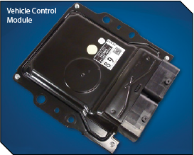
VCM (Vehicle Control Module)
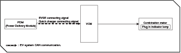
The VCM controls the EV system in a comprehensive manner as a gateway function for EV system CAN communication. The VCM judges the vehicle status according to signals from various sensors and ECUs. The VCM receives the information and transmits the signals to display: Li-ion Battery capacity, Available charge, Battery Temperature, Distance Range, Maximum Power, and Current Motor Power.
The VCM control logic for 2013 has been modified to provide more efficient control of energy usage with an extended regeneration range. Integrating the onboard charger into the PDM has resulted in modifications to the charging control logic. The electric shift control module is built into the VCM. Instead of the conventional mechanical shift mechanism, the electric shift system is adopted which electrically detects shifting operation and locks/unlocks the parking mechanism by operating the parking actuator.
The ECO switch is now a direct input to the VCM, no longer part of the shift switch input. The BCM, PDM, and TCU can all initiate the VCM CAN Wake-up signal. If the power switch is not set to READY mode, and the vehicle sits for 24 hours or longer, the VCM requests the PDM to supply charging voltage (13-14 volts) to the 12-volt battery for 4 minutes.
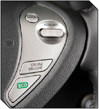
ECO mode no longer defaults to OFF when the vehicle is turned to OFF. If ECO mode is ON when the vehicle is turned OFF, it stays ON when restarting the EV system.