The new Q50 has some driver assistance systems that need to be maintained and aligned using special service tools and special procedures.

Active Lane Control
The Active Lane Control system monitors the lane markers on the traveling lane, using the camera unit located above the inside rearview mirror. The lane camera unit transmits the detected lane condition signal to the chassis control module via chassis communication.
Always adjust the camera aiming after removing and installing, or replacing the lane camera unit. The vehicle will need to be prepared before the camera aiming adjustment with CONSULT. To prepare the vehicle, do the following:
1. Perform general inspections: Clean the camera lens and windshield and check the lane camera unit condition (Ensure bracket is not bent and it is installed properly.).
2. Adjust the tire pressure to the specified pressure value.
3. Maintain no-load in vehicle.
4. Check if coolant and engine oil are filled up to the correct level and fuel tank is full.
5. Shift the selector lever to the P (Park) position and release the parking brake.

Use wheel chocks to the wheels to prevent the vehicle from moving.
NOTE: If any fixed object is on the instrument panel, cover the upper part of the instrument panel with black cloth to prevent an object from reflecting in the windshield.
Next, you will need to utilize special tool aiming adjustment target board. If you don't have the target board you can prepare an aiming adjustment jig by referring to the Driver Assistance section in your ESM, and print the “Work Procedure (Target Mark Sample)” to the specified size.
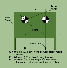
Assemble two target marks onto a white board as indicated in the illustration.
- Be sure to place the target correctly according to work procedures described in the ESM to ensure correct aiming alignment of the lane camera.
- When performing the target setting procedure, stage the vehicle on level ground. Place the vehicle where it is clear of any objects or obstruction around it. It is required that you have a clear view in front of the vehicle for 16.4 ft (5 m) and 9.84 ft (3 m) on both sides.
- Place the target in a well-lighted location. (Poor lighting may make it hard to correctly adjust the lane camera.)
- The target may not be detected correctly if there is a bright light source within 4.92 ft (1.5 m) from either side or within 3.28 ft (1 m) shining down on or reflecting up on the target.
- Bright sunlight should not be shining directly on the front of the vehicle as this can cause the lane camera to not perform correctly.
- If the vehicle is parked in direct sunlight under high temperature conditions, the lane camera functions may be suspended and the camera high temperature message will be indicated on the combination meter.
- The target may not be detected if there is a wall or surface with a similar dark and light pattern as the black and white target within 3.28 ft (1 m) from either side and upward/downward position from the target. (If possible, place the vehicle next to a single-color wall.)
TARGET SETTING
For target setting following tools, you will need a plumb bob, a chalk line or string, a marker, masking tape, and a tape measure with millimeters.
NOTE: You will need a tape measure long enough to measure 32.81 ft (10 m) or more.
1. Place the measuring tape even with the side of the left side tires. Start at the rear tire and go to the front tire.
- Extend the measuring tape approximately 13.12 ft (4 m) or more from the front end of vehicle.
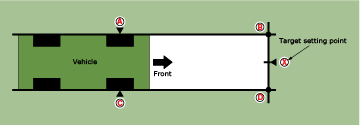
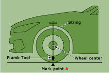
2. Hang the string with a plumb tool from the fender so that it passes through the center of the left front wheel, and then mark point A at the center of the lateral surface of the wheel on the floor on a piece of tape.
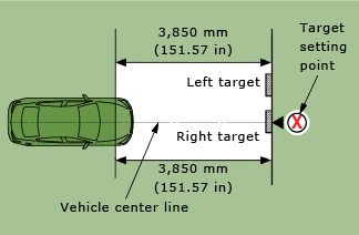
3. Measure and mark point B on the floor on a piece of tape at the position 151.57 in (3850 mm) from point A.
4. Remove the measuring tape.
Be careful not to move the vehicle or the marking points during the aiming procedure.
5. Now, place the measuring tape even with the side of the vehicle and repeat the measurements and marking on the right side tires. Again start at the rear tire and go to the front tire.
Extend the measuring tape approximately 13.12 ft (4 m) or more from the front end of the vehicle.
6. Hang a string with the plumb tool from the fender so it passes through the center of right front wheel, and then mark point C at the center of the lateral surface of the wheel on the floor on a piece of tape.
7. Measure and mark point D on a piece of tape at the position 151.57 in (3850 mm) from point C.
8. Remove the measuring tape. Now, snap a chalk line, or stretch out a string line and tape it in place for the “RH” passing through points C and D on the right side of the vehicle, and then do the same on the “LH” passing through A and B.
9. Place a measuring tape passing through the points B and D on the front side of the vehicle.
10. Mark point X at the center point between B and D on a piece of tape.
Make sure that X is in the center (at an equal distance between B and D).
11. Remove the measuring tape.
12. Position the center of the right target mark on the target board to align at the center X mark measurement to point of X.
NOTE:
- Be sure to place the target board so that the cross of the targets marks are horizontal and vertical.
- Fix point X with a plumb tool that hungs down from the right side target.
Perform the adjustment under an unloaded vehicle condition.
1. Measure the wheelarch height. Measure both sides of the front wheelarch height (Hf). Then calculate “Dh.”
To calculate “Dh,” use this formula: Dh [mm] = (Hf left side + Hf right side) ÷ 2 − 710 Hfl: Front left wheelarch height [mm] Hfr: Front right wheelarch height [mm]
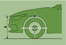
Be sure to measure wheelarch height correctly as these measurements are needed to input into CONSULT for aiming adjustment.
NOTE: The “Dh” measurement may be calculated as a minus value.
Camera Aiming Adjustment with CONSULT
Operate CONSULT from outside the vehicle, and close all the doors. The vehicle must be level, so you cannot be in the vehicle when performing aiming.
1. Select “Work Support” on “LANE CAMERA” with CONSULT.
2. Select “AUTO AIM.”
3. Confirm the following items:
- The target is accurately placed.
- The vehicle is not moving. Be careful not to bump it.
4. Select “Start” to perform camera aiming.
Never select “Start” when the target is not accurately placed.
Wait 5 seconds or more after selecting “Start.”
5. Input the “Dh” measurement you calculated into CONSULT, and then select “Start.”
Never change “Ht” and “Dt” when performing auto aim with CONSULT.
6. Confirm the displayed item.
Is “Normally Completed” displayed?
- YES >> Select “End” to close the aiming adjustment procedure.
- NO>> Determine and correct the possible cause, and then perform camera aiming again.
PERFORM SELF-DIAGNOSIS
Perform self-diagnosis of lane camera unit with CONSULT. If the camera unit passes selfdiagnosis, you are finished. If it fails, you will need to diagnose the concern and complete this procedure again.
Calibrating the Around View Monitor Camera Image
Perform camera calibration and perform writing to the Around View Monitor control unit, after removal or installation or replacement of each camera or camera mounting parts (front grille, door mirror or others), or replacement of the Around View Monitor control unit.
By performing this camera calibration procedure, the boundary of each camera image is aligned to the white lines on the road near the vehicle. The boundary of each camera image may not be aligned to the white lines far from the vehicle. The farther the line, the greater the difference.
Release Un-Match Display (Perform Only When Around View Monitor Control Unit Is Replaced)
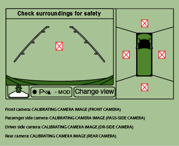
1. Using the CONSULT Work Support, select “CALIBRATING CAMERA IMAGE.”
NOTE: If the un-match display is on the screen, perform the operation for all cameras for which un-match display appears.
NOTE: In random order, perform the operation for all cameras for which un-match display appears.
2. On each camera calibration screen, press the “APPLY” button, and then press the “OK” button.
Never perform any operation other than selecting the “APPLY” button.
Never perform “INITIALIZE CAMERA IMAGE CALIBRATION.”
3. Display the Around View Monitor screen. Check that images are displayed normally without any un-match display icon images on the screen at any camera.
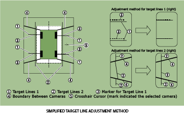
Perform Simplified Confirmation/Adjustment By “Fine Tuning the Birds-Eye View”
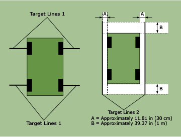
1. Put target line 1 beside each axle using white packing or duct tape, etc.
2. Put target line 2 at a position approximately 11.81 in (30 cm) away from each side of the vehicle (the left and right). Check that the target line is a length equivalent to the vehicle length, plus an additional approximate length of 39.37 in (1 m) (Ensure that the tape is lined up parallel with the vehicle as much as possible.).
3. With CONSULT in work support, select “FINE TUNING OF BIRDS-EYE VIEW.”
4. Select the left and right cameras on the CONSULT screen. Perform the following calibration.
- Check that target line 1 and marker are aligned normally on screen. If difference is detected, align the marker using the “+” and “–” of “AXIS X” and “AXIS Y” on the CONSULT screen.
- Check that target line 2 is aligned normally on screen without a difference between the images of each camera. If a difference is detected, align the images so that line 2 is displayed in a straight line, using the “+” and “–” of “AXIS X,” “AXIS Y” and “ROTATE” on the CONSULT screen.
NOTE: Press the “SELECT” button on the CONSULT screen and select camera position for adjustment.
- Never adjust the front camera and rear camera. Only adjust the side cameras drivers side and passenger side.
- Perform the adjustment operation slowly, because it takes approximately 1 second for the screen images to change.
5. Adjust the left and right cameras. Check that the difference of the images on screen between target line 1 and marker, and between target lines 2 are aligned. Press “APPLY.”
NOTE:
- The setting can be initialized to factory default condition, using “CALIBRATING CAMERA IMAGE” of CONSULT work support.
- The adjustment value on this mode is canceled when “INITIALIZE CAMERA IMAGE CALIBRATION” is performed.
- If the differences are corrected, select “OK” to end calibration. If the differences are not corrected, proceed to “Calibrating Camera Image.”
Perform “Calibrating Camera Image”
For target setting following tools, you will need a plumb bob, vinyl string, a marker, white
packing or duct tape, a tape measure with millimeters, and a large triangle scale.
NOTE: You will need a tape measure long enough to measure 59.06 in (1.5 m) or more.
Preparation Of Target Line
1. Hang a string with a plumb tool as shown in the figure. Mark the points FM0, RM0 (mark) on the ground at the center of the vehicle front end and rear end, using white packing or duct tape and a marker.
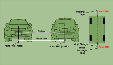
2. Route the vinyl string under the vehicle and pull it tight and straight. Affix the vinyl string at points approximately 39.37 in (1.0 m) from the front and the rear of the vehicle through points FM0 and RM0, using the white tape.
3. Next, measure and mark the FM and RM location points 29.53 in (75 cm) from the FM0 and RM0 points.
4. Route the vinyl string through points FM and RM using the triangle scale and then fix it at approximately 59.06 in (1.5 m) on both sides with the white tape.
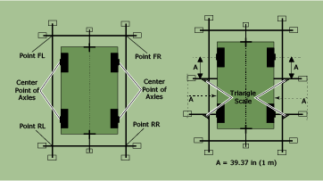
5. Measure and mark points FL, FR, RL and RR at a distance of half the vehicle width, plus 11.81 in (30 cm) to the left and right from points FM and RM.
6. Draw the lines of the points FL – RL and FR – RR by stretching out the vinyl string and taping it down to the ground with packing tape.
7. Put a mark at the center of each front axle. Then use a triangle scale to draw a line at the position measuring 39.37 in (1 m) backward from the mark placed at the center of front axle so that the line becomes perpendicular to the line drawn between point FLRL and point FR-RR and tape down with packing tape. Measure 39.37 in (1 m) outward from the vehicle front axle marks and place a large piece of white packing tape.
8. Put a mark at the center of each rear axle. Use a triangle scale to draw a line at the position that is perpendicular to the line drawn between point FL-RL and point FR-RR and tape down with packing tape. Measure 39.37 in (1 m) outward from the vehicle rear axle marks and place a large piece of white packing tape.
Perform “Calibrating Camera Image” Using CONSULT Work Support
1. Select “CALIBRATING CAMERA IMAGE.”
NOTE: In random order, perform the calibration operation for all cameras.
Front camera: “CALIBRATING CAMERA IMAGE (FRONT CAMERA)”
Passenger side camera: “CALIBRATING CAMERA IMAGE (PASS-SIDE CAMERA)”
Driver side camera: “CALIBRATING CAMERA IMAGE (DR-SIDE CAMERA)”
Rear camera: “CALIBRATING CAMERA IMAGE (REAR CAMERA)”
2. On each of the calibration screens: “REAR CAMERA,” “FRONT CAMERA,” “DR-SIDE CAMERA” and “PASS-SIDE CAMERA,” use the “+” and “–” of “AXIS X,” “AXIS Y” and “ROTATE” so that the images on screen depicting the target lines and the calibration markers are aligned.
3. Press the “APPLY” button on CONSULT screen. “Writing...” is displayed, and then the adjustment result is shown on the CONSULT display.
Confirm that “Writing...” is displayed on CONSULT. Never perform any other operations while “Writing...” is displayed.
4. Press the “APPLY” button on CONSULT screen. “Writing...” is displayed, and then the adjustment result is written to the Around View Monitor control unit.
Perform “Fine Tuning Of Birds-Eye View”
This “Fine Tuning of Birds-Eye View” is designed to align the boundary between each camera image that cannot be aligned in the “CALIBRATING CAMERA IMAGE” mode.
1. Using CONSULT work support, select “FINE TUNING OF BIRDS-EYE VIEW.”
2. Operate the “+” and “–” of “AXIS X,” “AXIS Y” and “ROTATE” so that the images on the screen of the target line on the ground and marker are aligned between each camera.
Perform the adjustment operation slowly, because approximately 1 second is required for changing image on screen.
NOTE: Press the “SELECT” button on the CONSULT screen to select each camera position (FRONT, PASS-SIDE, DR-SIDE, and REAR) for adjustment.
3. Press the “APPLY” button on CONSULT screen. “Writing...” is displayed, and then the adjustment result is shown on the display.
Check that “Writing...” is displayed. Never perform other operations while “Writing...” is displayed.
After selecting “OK,” never perform any operation other than “BACK” on CONSULT
4. Press the “APPLY” button on the CONSULT screen. “Writing...” is displayed, and then confirm the adjustment result is written to Around View Monitor control unit.
NOTE:
- The calibration settings can also be initialized to the factory default setting, using “CALIBRATING CAMERA IMAGE” of work support.
- Any adjustment values written to the Around View control unit will be canceled when “INITIALIZE CAMERA IMAGE CALIBRATION” is performed.
Adjust the center position of the predictive course line of the front view and rear view monitor.
Rear View Monitor Predictive course line center position adjustment.
Drive the vehicle straight ahead 328.1 ft (100 m) or more
at a speed of 18.6 MPH 30 km/h or more.
Around View Monitor Predictive course line center position adjustment.
Drive the vehicle straight ahead 328.1 ft (100 m) or more at a speed of 18.6 MPH 30 km/h or more.
Vehicles with Direct Adaptive Steering
Direct Adaptive Steering Re-calibration
During the Pre-Delivery Inspection (PDI) test drive, while driving
straight you may experience the following conditions:
- While driving straight, the steering wheel is off-center
- While driving straight, if you relax your grip on the steering, the steering wheel will return to center and the vehicle will pull, as if making a turn. The above conditions indicate the Direct Adaptive Steering (DAST) needs to be re-calibrated.
To re-calibrate the Direct Adaptive Steering:
1. With the vehicle safely parked, turn the ignition OFF and then ON.
2. Turn the steering wheels left 90 degrees from center and then turn the steering wheel right 90 degrees from center. Repeat the steering wheel turns.
3. Drive the vehicle onto a smooth, straight, flat road.
4. While driving straight hold the steering wheel so the vehicle stays in a straight line at a speed of 20 mph or more for at least 5 seconds.
When performing the drive to re-calibrate the DAST, the steering wheel will slowly adjust to a center position while you continue to drive straight correcting the off-center condition.
NOTE: It’s necessary to perform this procedure on a smooth straight drive. Pot holes, bumps on an uneven road surface, or traffic conditions that require steering input may affect the calibration. If you experience this during your drive, repeat the DAST re-calibration steps 1-4.