![]()
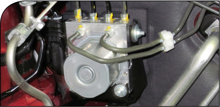
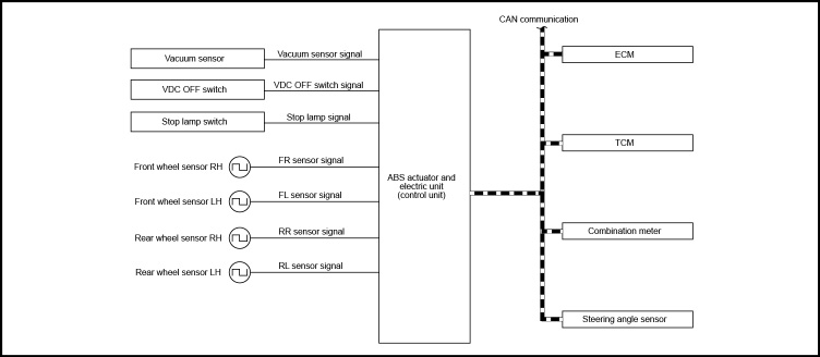
The Electric Control Unit (ECU) on the 2013 L33 Altima is integrated with the actuator to comprehensively control the VDC, TCS, ABS and EBD function. When replacing the ABS actuator and electric control unit, calibration of the ABS actuator and electric control unit is required.
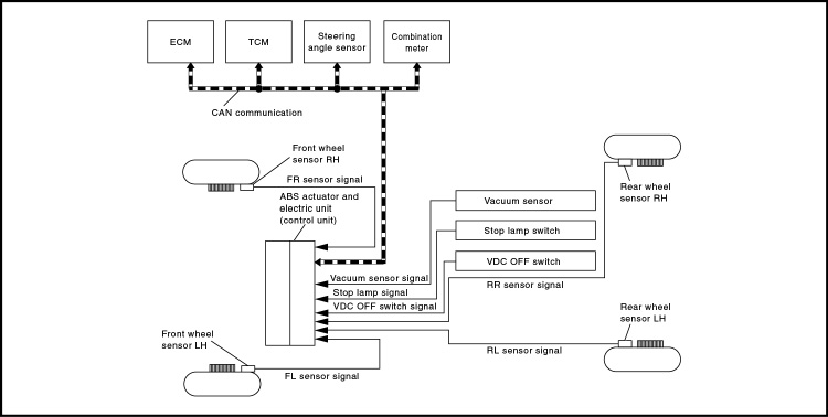
If you need to replace a VDC actuator for any reason on the 2013 Altima sedan, it is also necessary for you to perform a procedure to calibrate the variant coding on the new unit. Additionally, after replacing the ABS actuator and ECU, you'll need to perform a steering angle sensor neutral position calibration. Configuration includes the following functions:
Read/Write Configuration
Before replacing ECU - Read the vehicle specification (Type ID) written in ABS actuator and ECU to store the specification in CONSULT.
After replacing ECU - Allows the writing of vehicle information (Type ID) stored in CONSULT into the ABS actuator and ECU.
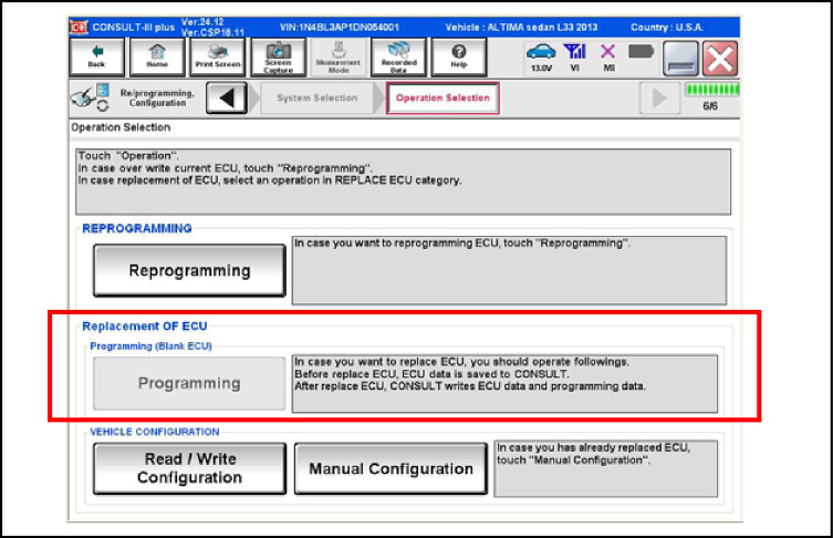
Manual Configuration
You'll need to perform ''Manual Configuration'' only when the ''TYPE ID'' of ABS actuator and electric unit (control unit) cannot be read. Manual configuration allows you to write the vehicle specification (Type ID) into the ABS actuator and ECU by hand with manual selection saving the ECU files based on how the vehicle is equipped.
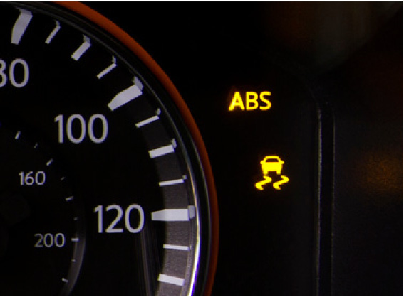
- After configuration, press the ignition switch from OFF to ON and confirm that the VDC warning lamp turns "OFF" (after it illuminates for approximately two seconds).
- If an error occurs while performing configuration, you must start over from the beginning.
Work Procedure
1. CHECK TYPE ID using FAST
Use the Nissan Electronic Parts Catalog (WIN FAST or equivalent), to search for the ABS actuator and ECU of the applicable vehicle to find the "Type ID".
Is "Type ID" displayed?
YES>> Print out the "Type ID" and Go To 2.
NO>> Configuration is not required for the ABS Actuator and electric control unit.
2. CHECK TYPE ID on CONSULT
a. Select the "Before Replace ECU" button of "Read/Write Configuration" on CONSULT.
b. Check to be sure that the "Type ID" is displayed on the CONSULT screen.
Is "Type ID" displayed?
YES>> Go To 3.
NO>> Go to Work Procedure with CONSULT (Manual Writing) "Replace the ABS Actuator and ECU".
3. VERIFY TYPE ID
Compare the "Type ID" displayed on the CONSULT screen with the one you found in the FAST (service parts catalogue) to confirm that they match.
Remember: When searching for the "Type ID" using FAST, use the last five digits of the "Type ID".
4. SAVE TYPE ID
Next, save the "Type ID" on CONSULT.
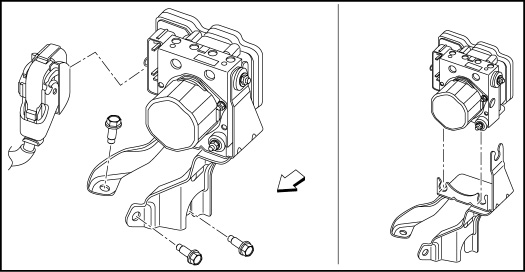
5. REPLACE the ABS ACTUATOR AND CONTROL UNIT (Refer to the BRC-Removal and Installation section of the ESM)
NOTE: DO NOT perform air bleeding at this time.
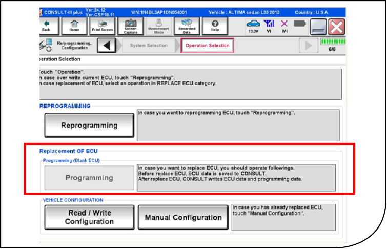
6. PERFORM (AUTOMATIC WRITING)
a. Select the "After Replace ECU" button of "Re/programming, Configuration" on CONSULT or that of "Read / Write Configuration".
b. Select the "Type ID" that matches with the one stored on CONSULT and the one you found in the FAST (service parts catalogue) list to write the "Type ID" into the ABS actuator and ECU.
7. VERIFY the TYPE ID
Compare "Type ID" written into the ABS actuator and ECU with the one provided by the FAST (service parts catalogue) and confirm that they match.
8. CHECK the VDC WARNING LAMP
After configuration, turn the ignition switch from OFF to ON, and then check that the VDC warning lamp turns OFF after staying illuminated for approximately two seconds.
![]()
Do not start the engine while checking the VDC warning lamp. The VDC OFF indicator lamp turns OFF (standby status) when the engine is started.
Is the inspection result normal?
YES>> Go to 9.
NO>> Perform the self-diagnosis of "ABS". Refer to "CONSULT Function (ABS)."
9. PERFORM THE SUPPLEMENTARY WORK
a. After work is completed, bleed the air from the brake tube. Refer to the applicable ESM BR-Section for "Bleeding Brake System" procedure.
b. Perform the self-diagnosis of all systems.
c. Erase self-diagnosis results.
Work Procedure with CONSULT to Perform Manual Configuration (Manual Writing)
1. REPLACE the ABS ACTUATOR and ECU
a. Select "Manual Configuration."
b. Select the "Type ID" that matches the one taken from the FAST (service parts catalogue) to write the "Type ID" into the ABS actuator and ECU.
When searching for the "Type ID" using the FAST (service parts catalog), use the last five digits of the "Type ID."
2. VERIFY the TYPE ID Compare "Type ID" written into the ABS actuator and ECU with the one provided by the FAST (service parts catalogue) and confirm that they match.
3. CHECKING THE VDC WARNING LAMP After configuration, turn the ignition switch from OFF to ON, and then check that the VDC warning lamp turns OFF after staying illuminated for approximately two seconds.
![]()
Do Not start the engine while checking the VDC warning lamp. The VDC OFF indicator lamp turns OFF (standby status) when the engine is started.
Is the inspection result normal?
YES>> Go to 4.
NO>> Perform the self-diagnosis of "ABS." Refer to "CONSULT Function (ABS)."
4. PERFORM THE SUPPLEMENTARY WORK
a. After work is completed, bleed the air from the brake tube. Refer to the applicable ESM BR-Section for "Bleeding Brake System" procedure.
b. Perform the self-diagnosis of all systems.
c. Erase self-diagnosis results.
THINGS TO REMEMBER
- Never perform air bleeding prior to replacing the ABS actuator and ECU, bleed air from brake tubes after work is completed.
- If the ABS actuator and ECU are replaced, you'll also need to adjust position of steering angle sensor after installing the new parts.
ADJUSTMENT OF STEERING ANGLE SENSOR NEUTRAL POSITION
NOTE: To adjust the steering angle sensor neutral position make sure to use CONSULT (Adjustment cannot be done without CONSULT).
1. Align the vehicle with the front wheels in straight-ahead position.
>> GO TO 2.
2. Peform the Neutral Position Adjustment for the steering angle sensor.
a. On the CONSULT screen, touch "WORK SUPPORT" and "ST ANG SEN ADJUSTMENT" in order.
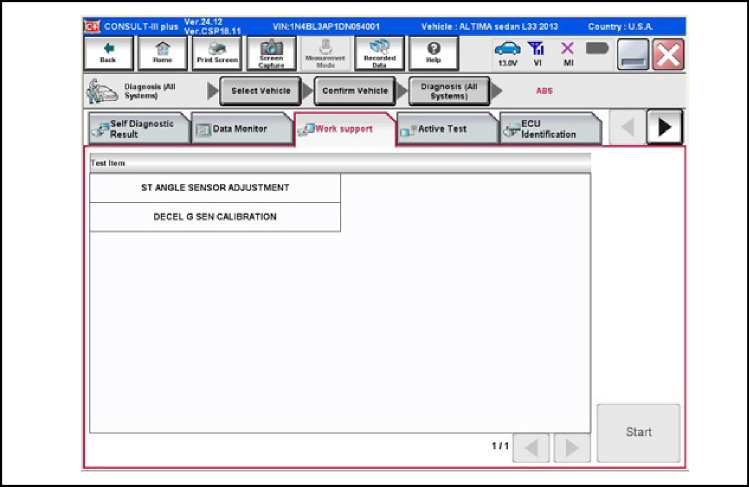
b. Touch "START."
![]()
Do Not touch the steering wheel while adjusting the steering angle sensor, to ensure that the steering wheel remains in the straight-ahead neutral position.
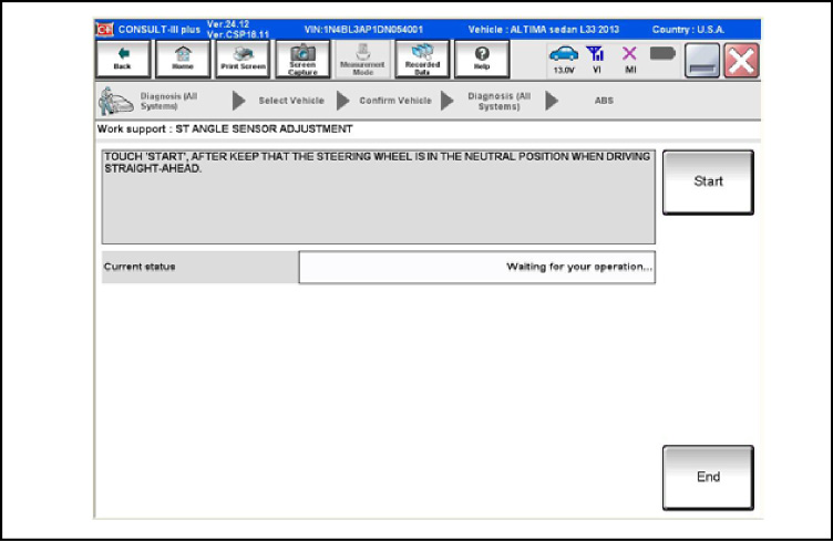
c. After approximately 10 seconds, touch "END."
NOTE: After approximately 60 seconds, it ends automatically.
d. Turn ignition switch OFF, then turn it ON again.
![]()
Be sure to perform the ignition OFF/ON operation (to confirm procedure).
>> GO TO 3.
3. CHECK DATA MONITOR
a. Run vehicle with front wheels in straight-ahead position, then stop.
b. Select "DATA MONITOR." Then make sure "STR ANGLE SIG" is within 0±2.5°. Is the steering angle within the specified range?
YES>> GO TO 4.
NO>> Perform the neutral position adjustment for the steering angle sensor again, GO TO 1.
4. Erase the self-diagnosis memory of the ABS actuator and ECU and ECM.